S/M No: RNU20IB001 Refrigerator FRN-U20IB* FRS-U20IB* FRU-577I~ FRN-U20DB* FRN-U20EB* FRS-U20DB* FRS-U20EB* FRU-547D/E~ FRN-U20FB* FRN-U20GB* FRS-U20FB* FRS-U20GB* FRU-547F/G~ ✔ Caution : In this Manual, some parts can be changed for improving, their performance without notice in the parts list.
CONTENTS 1. WARNINGS AND PRECAUTIONS FOR SAFETY ----------------------------2 2. EXTERNAL VIEW 2-1. External Size ---------------------------------------------------3 2-2. Name of Each Parts ------------------------------------------6 2-3. Cold Air Circulation ----------------------------------------------8 3. SPECIFICATION --------------------------------------------------9 4. OPERATION AND FUNCTIONS --------------------------------------11 5. CIRCUIT OPERATION 5-1.
1. WARNINGS AND PRECAUTIONS FOR SAFETY Please observe the following safety precautions in order to use safely and correctly the refrigerator and to prevent accident and danger during repair. 1. Be care of an electric shock. Disconnect power cord from wall outlet and wait for more than three minutes before replacing PCB parts. Shut off the power whenever replacing and repairing electric components. 2.
2. EXTERNAL VIEWS 2-1.
- FRS(N)-U20DB / EB 4
- FRS(N)-U20FB / GB 5
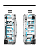
2-2. Name of Each Parts - Basic Model 6 1 2 7 3 8 4 9 10 11 5 12 - Wine Rack is option Freezer Compartment Refrigerator Compartment 1. Freezer light 6. Dairy pocket 2. Freezer pocket 7. Refrigerator light 3. Ice tray 8. Chilled case 4. Freezer shelf 9. Movable Egg case 5. Freezer case 10. Refrigerator shelf 11. Refrigerator pocket 12.
- Full option Model 7 1 2 3 8 9 4 10 11 5 12 6 13 -Full option Model illustrated. -Features are model dependent. Freezer Compartment Refrigerator Compartment 1. Ice cubes storage case 7. Dairy pocket 2. Freezer light 8. Refrigerator light 3. Water/Ice Dispenser 9. Wine Rack 4. Freezer shelf 10. Movable Egg case 5. Freezer pocket 11. Refrigerator shelf 6. Freezer case 12. Refrigerator pocket 13.
2-3.
3. SPECIFICATION 3-1.
Item Model Name D E F O R E S T H E A T E R E L E C T R I C A L P A R T S Specification ( 220~240V Models only ) Basic Model Dispenser Model D-Sensor PBN-43 F-Sensor PBN-38 R-Sensor PBN-43 Defrost Heater AC220V / 192W Main Duct Heater AC220V / 7W Louver Heater AC220V / 8W Dispenser Heater - AC220V / 5W Water Pipe Heater - AC220V / 5W Main Fuse (Power cord) AC250V 15A Fuse Temp (Defrost) AC250V , 10A , 77℃ F-Fan Motor DC13V / 2050±100 rpm R-Fan Motor DC13V / 1950±100 rpm Conden
4. OPERATION AND FUNCTIONS 4-1. Display 4-1-1. Basic Model INPUT CONTROL OBJECT FRZ.TEMP, REF.TEMP Inner Control (Lamp-LED) CONTENTS REMARKS Temperature adjustment button for freezer compartment. Temperature adjustment button for refrigerator compartment. 1. “FRZ.TEMP” Button 1) Temperature control of Freezer compartment 2) 5 step mode of successive temperature mode.
4-1-2. Dispenser Model INPUT CONTROL OBJECT Front PCB button FREEZER SET, REFRIGERATOR SET SUPER FREEZER, SUPER REFRIGERATOR RESET FILTER, WATER / ICE, ICE MAKER LOCK ,LOCK FCP C-LED CONTENTS Water filter reset REMARKS Dispenser select button Ice maker lock button Super freezer Lock button Super Refrigerator Temperature adjustment button for freezer compartment. Temperature adjustment button for refrigerator compartment. 1. Display control FCP-LED Control 88 DISPLAY (SET TEMP.
CONTENTS REMARKS 4. “REFRIGERATOR SET” button. 1) Temperature control of Refrigerator compartment 2) 5 step mode of successive temperature mode. 3) Initial mode by power input : “Medium (4℃)” ※Whenever pressing button, setting is repeated in the order of Medium (4℃) → Medium Max (3℃) → Max (2℃) → Min (6℃) → Medium Min (5℃). Letters are indicated on 88 Display LED Temperature Change Min Medium Min Mid Medium Max Max Temp indication 6℃ 5℃ 4℃ 3℃ 2℃ 5. “SUPER REFRIGERATOR” button.
4-2. Defrost Mode INPUT CONTROL OBJECT 1. Comp 2. F-Fan 3. R-Fan 4. D-Heater 1. Defrosting Cycle CONTENTS REMARKS 1. Defrost Mode Pre-Cool Heater Defrosting Pause Fan-Delay Pre-Cool 1) Time : 50 minutes 2) Comp , F-fan : ON R-fan : Control D-HTR : OFF 3) If F-sensor ≤ -27℃, then Pre-Cool becomes.
CONTENTS REMARKS 4. Flow Chart of Defrosting Start Start Comp. operating time is over 2 hours? NO YES YES Total time is over 60 hours? NO YES Comp. operating time is over 24 hours? NO Comp. operating time is over 6 hours? YES YES Comp.
4-3. (Forced Defrosting) Mode INPUT CONTROL OBJECT 1. Comp 2. F-Fan 3. R-Fan 4. D-Heater 1. Defrosting Cycle CONTENTS REMARKS 1.
4-5. Louver Heater Control INPUT CONTROL OBJECT Louver Heater 1. Comp CONTENTS REMARKS It is linked with comp. 4-6. Buzzer or Alarm Control INPUT CONTROL OBJECT 1. Control (Inner or F-PCB) buttons 2. Door Switch 3. Initial Power Input Buzzer CONTENTS REMARKS 1. Buzzer sounds if any button of Inner Control is pushed. 2. Buzzer sounds 4 times 3 seconds after initial power input. 3. Buzzer sounds for 3 or 1 times in case of A/S forced defrosting and short (pull down) operation or explanation mode.
4-8. Demonstration 4-8-1. Basic Model INPUT CONTROL OBJECT Comp F/R-Fan Heater 1. FRZ. TEMP 2. Door Switch CONTENTS REMARKS 1. Start Open and close “Freezer door switch” 5 times while pushing “FRZ. TEMP” button simultaneously. 2. Control 1) All other electrical components are OFF except for F-fan / R-fan 2) Fan Control Door open → Fan ON / Door close → Fan OFF. 3) Display control “FRZ. LED” and “REF. LED” are ON in good order 3.
4-9. Compensation of R-sensor ON/OFF Point INPUT CONTROL OBJECT Resistance of R-sensor Mid ON/OFF Point Main PCB CONTENTS REMARKS Compensation of R-sensor ON/OFF temp. (down) In case temperature of refrigerator compartment is weak or insufficient, take the following action. FRS(N)-U20IA FRS(N)-U20DA R-SENSOR R36 R36 R37 R37 R38 ※ Refer to the 5-2. (Function of each sensor) R-SENSOR J2 R38 J1 J19 J1 J18 J18,19 J2 R36 : R-SENSOR standard resistance in normal mode (31.
4-10. Error Display 4-10-1. Basic Model (LED Display of Inner Control) INPUT CONTROL OBJECT Temperature Control Buttons Lamp LED of Inner control CONTENTS REMARKS 1. How to start 1) Press “FRZ.TEMP” button 5 times while pressing “REF.TEMP” button at the same time. 2. How to stop 1) Push “FRZ.TEMP” button 1 time. 2) It stops automatically in 4 minutes from the start. 3. All the error codes are reset if they turn to be normal. 4.
CONTENTS REMARKS 5. Control way of Errors (if any) 1) “F-sensor” error Cause : F-sensor open or short Control : Condition of ambient temperature How to reset : If F-sensor is normal, the error is terminal temperature. RT-S ~ 9℃ ~ 15℃ ~ 21℃ ~ 31℃ ~ 41℃ Over 41℃ ON/OFF (min) 14 / 50 16 / 41 27 / 45 26 / 22 35 / 20 35 / 20 2) “R-sensor” error Cause : R-sensor open or short Control : Condition of ambient temperature How to reset : If R-sensor is normal, the error is terminal temperature.
4-10-2. Dispenser Model (CLED Display of Front PCB) INPUT CONTROL OBJECT Temperature Control Buttons 88 Display CLED CONTENTS REMARKS 1. How to start 1) Under “LOCK” mode, press “SUPER FREEZER” button 5 times while pressing “FREEZER SET” button at the same time. 2) The front CLED displays as the right diagram shows ( [Ex.] Time Display of 0003 signifies 3 minutes of power on time.) 3) Press “FREEZER SET” button and the following value is displayed successively.
CONTENTS REMARKS 5. Control way of Error (if any) 1) “F1” error Cause : F-sensor disconnection or short Check point : Measure the resistance between both terminals after separating CN8 (or CN15) of the Main PCB. (Refer to the 5-2.) If F-sensor is disconnected or shorted , change the F-sensor in the freezer compartment. How to reset : If F-sensor is normal, the error is terminal temperature.
CONTENTS REMARKS 9) “EI”ERROR Cause : I-SENSOR disconnection / short Check point : Measure the resistance between both terminals after separating CN11 of the Main PCB. (Refer to the 5-2.) If F-sensor is disconnected or shorted , change the I-sensor in the automatic ice maker. 10) “EF” ERROR Cause : When Flow-sensor ERROR (There is no Pulse during some time) The number of pulse signal is below 10 by 1 sec during water supply.
4-11. Summary of Function 4-11-1. Basic Model (Inner Control) INPUT CONTROL OBJECT Each button Resistance of R-sensor Mid ON/OFF Point CONTENTS REMARKS Element A/S Function Forced Defrosting “FRZ.TEMP” + “REF.TEMP” 5 times Pull Down “REF.TEMP”+ “FRZ.DOOR” OPEN/CLOSE 5 times Demo function “FRZ.TEMP”+ “FRZ.DOOR” OPEN/CLOSE 5 times Error display “REF.TEMP”+ “FRZ.TEMP” 5 times 4-11-2.
4-12. Back up Function (Basic Model) INPUT CONTROL OBJECT None 1. F-FAN, R-FAN, C-FAN CONTENTS REMARKS 1. Filter Exchange Information : Record as a real-time from the point of power input 2. P Factor (Information about Ice Maker) 4-13. Automatic Icemaker ( Dispenser Model) INPUT CONTROL OBJECT Full ice sensing switch Ice Maker Lock Sensors Ice separating motor CONTENTS REMARKS 1.
CONTENTS REMARKS 2) With the initial power input, Ice tray turns to be horizontal and ice making mode starts. 3) Control of water hose heater * Heater is always ON if RT-sensor has an error or RT is below 15 degree. * Heater is always ON for 60 minutes (max.
CONTENTS REMARKS 3. Ice separating (drop) mode status of ice tray Ice separation start Horizontal position level SW 8~11sec normal level SW motor revolution level SW error MAX1.1sec 8.5~12.2sec CW CCW 10 sec 11 sec 0.2sec CW STOP 1.1 sec 1) Time of each zone used to verify level switch error 2) The rotation of motor is sensed at each zone 3) In case of level switch error, ice separation is done by time. 4) If ice separating motor has error, the mode stop. 4.
CONTENTS 1) REMARKS Water supply valve is open when water supply mode starts after separation of ices. 2) Water is supplied by time in case sensor has error. 3) Factor valve is variable which can be useful in AS action ① Water flow pulse is set to 238 if flow sensor is in normal condition. (If water is supplied by time, maximum water supply time 165 seconds) ② In case water flow sensor has error, water time is 5.5 seconds. 5.
CONTENTS REMARKS 4) Control Flow & Timing Chart ① Crushed Ice D.P SW D.P Lamp D.P S/V (Flap) D A C A Gear Motor ② Cubed Ice D.P SW A D.P Lamp D B A Cube S/V D.P S/V (Flap) C A Gear Motor ③ Water D.P SW D.P Lamp D A Water S/V Delay time : A = 500ms, B = 500ms, C = 2.0s, D = 5.
5. CIRCUIT OPERATION 5-1. Power Circuit Diagram - Basic Model A B D C E - Dispenser Model A B D C E ※ Voltage of every part Parts Voltage A MC1 230Vdc B CE1 310Vac C CE3 12Vdc D CE4 14.5Vdc E CE6 5Vdc ※ Caution : Since high voltage (DC310V) is maintained at the power terminal, please take a measure after more than 3minutes have passed after removing power cords in the abnormal operation of a circuit.
5-2. Function of Each Sensor - Dispenser Model CONTENTS REMARKS Compensation of R-sensor ON/OFF temp. B C A [F-sensor] 1) It senses the temperature of freezer compartment and control Comp., F-fan ON/OFF 2) How it works; Working Point Working Temp. Resistance Sensing Voltage Low ON -11℃ ≒9.32㏀ ≒3.24V Mid OFF -16℃ ≒15.19㏀ ≒2.93V High OFF -19℃ ≒15.58㏀ ≒2.73V [R-sensor] 1) It senses the temperature of refrigerator compartment and control R-fan ON/OFF 2) How it works; Working Point Working Temp.
- Dispenser Model CONTENTS REMARKS Compensation of R-sensor ON/OFF temp. IC1 (MICOM) B C A D [F-sensor (A)] 1) It senses the temperature of freezer compartment and control Comp., F-fan ON/OFF 2) How it works; Working Point Working Temp. Resistance Sensing Voltage Low ON -11℃ ≒9.32㏀ ≒3.24V Mid OFF -16℃ ≒15.19㏀ ≒2.93V High OFF -19℃ ≒15.58㏀ ≒2.73V [R-sensor (B)] 1) It senses the temperature of refrigerator compartment and control R-fan ON/OFF 2) How it works; Working Point Working Temp.
5-3. Relay Function - Basic Model CONTENTS REMARKS 1. Circuit Diagram IC1 (MICOM) Comp Comp R-Lamp Louver Heater F-Lamp D-Heater Louver Heater D-Heater 2. How it works; ON Condition Control Control Mode Method MICOM Port Comp Relay 1 #1≒5.0V Louver Heater Relay 3 #3≒5.0V D-Heater Relay 5 #5≒5.0V OFF Condition IC ULN2004 Output pin IC7 34 MICOM Port #10≒0.7V #1≒0V #12≒0.7V #3≒0V #14≒0.
- Dispenser Model CONTENTS REMARKS 1. Circuit Diagram IC1 (MICOM) Comp R-Lamp Louver Heater F-Lamp D-Heater 2. How it works; ON Condition IC ULN2004 Output pin OFF Condition IC ULN2004 Output pin Control Control Mode Method MICOM Port Comp Relay 1 #1≒5.0V #10≒0.
5-4. Fan Function 1. Circuit Diagram - Basic Model - Dispenser Model 2. Explanation for the operation * TA7291P is the drive IC for the only DC motor, and used for control of the fan motor * One input and output is used for the control of the fan motor Input Motor IC No.5 Pin (R:MT2/F:MT3/C:MT1) High Low Output Motor IC No.
6. DIAGRAM 6-1.
- Dispenser Model 38
6-2.
40
- Dispenser Model 41
42
7. COMPONENT LOCATE WIEW 7-1. Front View ( Dispenser + Home bar Model ) Front PCB Home bar Door (Option) Dispenser Button 7-2.
7-3. Evaporator Water Pipe D-Sensor Temp Fuse Evaporator Defrost Heater 7-4.
8. HOW TO CHECK EACH PARTS 8-1. Hose Ice Maker Tube Assembly 1) Disassembling Procedure NO DISASSEMBLING PROCEDURE NO 1 DISASSEMBLING PROCEDURE 5 ▷Remove 2 screws at the Cove Guide Cab W/Tube A. ▷Pull forward Ice Storage Case 2 6 ▷Remove 2 screws. ▷Disassemble Cover Guide Cab W/Tube A 3 7 ▷Pull forward Ice Maker. ▷Pull forward Hose Ice Maker Tube As. 4 8 ▷Check Hose Ice Maker Tube As. ▷Remove Water Hose Heater's 2P housing. 2) How to check Hose Ice Maker Tube As.
8-2. Bracket Geared Motor Assembly 1) Disassembling Procedure NO DISASSEMBLING PROCEDURE NO 1 DISASSEMBLING PROCEDURE 4 ▷Remove 2 screws. ▷Pull forward Bracket Geared Motor. 2 5 Unscrew (red 4 screws). Unscrew (blue 4 screws). ▷Unscrew (4 points). 3 6 ▷Separate 6 pin housing of Bracket Geared Motor from the top connector. ▷Check Solenoid Valve and Geared Motor. 2) How to Check Hose Ice Maker Tube Assembly PARTS Geared Motor SPEC. HOW TO CHECK CRITERION ▷SPEC.
8-3. Dispenser Micro Switch 1) Disassembling Procedure NO DISASSEMBLING PROCEDURE NO 1 DISASSEMBLING PROCEDURE 3 ▷ Insert (-) screw driver into bottom hole of Dispenser Button Guide. Pull up forward to remove the guide. (Be careful not to damage guide surface.) ▷Separate wire connectors from Micro Switch. 4 2 ▷Check Micro Switch. ▷ Remove Micro switch. 2) How to Check Micro Switch PARTS HOW TO CHECK CRITERION ▷GOOD : SPEC.
8-4. Dispenser Solenoid Valve 1) Disassembling Procedure NO DISASSEMBLING PROCEDURE NO 1 DISASSEMBLING PROCEDURE 4 ▷ Insert (-) screw driver into bottom left groove of Cover Dispenser Box. Pull forward with a snap.(Be careful not to damage cover and door surface.) ▷Separate 2 terminals from Sol Valve and 2P Housings from Cover Ice Flap. 2 5 ▷ Separate 2 housings of 10P / 7P from Front PCB. (Do not hold only wires to pull out.) ▷Unscrew (3 points) to remove Sol Valve.
8-5. Main PCB - Basic Model 1 6 3 2 5 4 NO 1 ITEM CHECK POINT Compensation of Weak Refrigeration →Making R-temp cooler 2 Relay Power Controller 3 Fan Power Controller REMARK * Used when making R-temp. down to compensate for weak refrigeration without changing FCP temp. setting. ▷Cutting of J1 ; down by 1.5℃ ▷Cutting of J1, J2 ; down by 3℃ J1 J2 * To check normal voltage of each electrical devices to & from Mi-com.
- Dispenser Model 1 6 3 5 2 4 NO ITEM 1 Compensation of Weak Refrigeration →Making R-temp cooler 2 Relay Power Controller 3 Fan Power Controller CHECK POINT REMARK * Used when making R-temp. down to compensate for weak refrigeration without changing FCP temp. setting. ▷Cutting of J18 ; down by 1.5 ℃ ▷Cutting of J18, J19 ; down by 3℃ J18,19 * To check normal voltage of each electrical devices to & from Mi-com. ▷Check input & output voltage of MICOM and IC7, 8.
8-6. Ice Maker 1) Disassembling Procedure NO DISASSEMBLING PROCEDURE NO 1 DISASSEMBLING PROCEDURE 6 ▷ Remove 2 screws on top front of ice maker. ▷Remove full ice sensing switch and level switch. 2 7 ▷ Pull forward ice maker. ▷Unscrew (3 points) Plate Gear Fixture. 3 8 ▷ Check if ice dropping motor is normal (OK). ▷Unscrew Fixture of Frame Ice Maker. 4 9 ▷Separate Ice Maker Assembly from Frame Ice Maker. ▷Remove 2 pin housing from Plate Gear Fixture.
2) How to Check Ice Maker PARTS HOW TO CHECK CRITERION ▷ GOOD : RS-360RH-14250 : 6 ~ 14Ω Ice Dropping Motor ▷ DEFECTIVE : Change the motor. ▷ Check resistance value of 2 wires with a Multi Tester. ▷ GOOD : 4.4 ~ 50kΩ (It depends on surround temp.) I-Sensor (Ice Sensor) ▷ DEFECTIVE : Change the sensor. ▷ Check resistance value of 2 wires with a Multi Tester. ▷ GOOD : Full Ice Sensing Switch ▷ Check resistance value of 2 terminals with a Multi Tester.
9. TROUBLE DIAGNOSIS 9-1. Faulty Start (F/R lights OFF , F-PCB Power OFF) Start Power cord or Fuse is disconnected ? Y Change the Main Fuse (AC250V 15A) N 1’st power of SMPS is on? (In the left side of machine compartment) N Check power Cord connection from machine compartment and to CN1 of M-PCB. Y Main PCB Fuse is disconnected? Y Change the Fuse (AC250V 3.15A) (on the Main PCB) N Voltage (DC12V/14.5V/5V) on Main PCB is OK? Y Wire connection of F-PCB is OK? N ※ Refer to the 5-1.
9-2. Freezer Compartment 9-2-1. Freezing failure . (Foods are not frozen / cold.) Start Y Any Error code on F-PCB? Refer to error display in operation and function N ※ Refer to the 4-10. (Error Display) N Does Comp. work? Y Y OLP/PTC is OK? N Change the Comp. Change OLP/PTC F/C-Motor works OK? N N F/C-Motor is OK? Change F/C-Motor Y Y Wiring connection Is OK? Y Change M-PCB N Check lead wire Temp. Fuse Is OK? N Change Fuse.
Removing and replacing Freezer parts (1) 1) Remove foods. 2) Remove Ice Bucket, shelves and cases in Freezer compartment. (2) (3) (4) * Remove 2 screws of Ice Maker. * Remove the Housing of Ice Maker AS. (Right side) 55 (5) * Remove 4 screws of Geared Motor. * Remove the Housing of Geared Motor AS.
Removing and replacing Freezer parts (6) (12) * Remove the screw cap on the F-Louver A with a flat tip driver. * Remove light cover screws. (7) (13) * Pull down smoothly the bottom of light cover to remove. * Remove 3 screws of F-Louver A. (8) (14) * Hold the end of F-Louver A and pull forward slowly. * Remove the screw of bracket F-Lamp. (9) * Remove the left housing. (15) * Remove the housing. (10) (16) * Pull out smoothly the bracket F-Lamp AS. to remove.
Removing and replacing Freezer parts D-Sensor Housing F-Louver B Heater Housing Temp. Fuse Housing 1st : F-Louver B Heater Housing 2nd : None. 3rd : Defrost Heater Housing. Temp.
9-2-2. Ice Formation on F-Louver Start Dews are formed on the gasket surface inside F compartment ? Y Gasket has a gap between cabinet ? Y Remove the gap. N N Door is hanged down ? Y Reassemble the door. N Door is open and closed too frequently ? Y Explain not to open doors too frequently. N Heat appliances are too close to the refrigerator ? Y Make enough distance between heat appliances and refrigerator.
9-2-3. Disconnection / breaking of Freezer Lights Wires Start Freezer light filament is disconnected or breaking ? Y N Connection of F door switch is OK ? Change the light bulb. N Repair the F-door switch. Y Check the F door switch connection and F-light socket. Change of F Lights ① ② Change of F Door Switch * Remove 2 screws of light cover. ① * Hold the bottom of light cover and pull forward to remove. ② * Insert a flat tip screw driver Into a gap of door switch to pull forward.
9-3. Refrigerator Compartment 9-3-1. Refrigeration failure (Foods does not get cool or cold soon.) Start Any error mode on F-PCB? ※ Refer to the 4-10. (Error Display) Y Solve error code problem, if any. N R-Motor works OK ? N Change the R-Motor. Y Y R-Sensor is OK (normal) ? N R-Motor is OK ? Y Wiring connection Is OK ? N Change the Main PCB. N Check the wirings. Y Freezer compartment Is OK ? Change the R-Sensor and check connector. N Refer to “Freezing does not work.
9-3-2. Disconnection / Breaking of Refrigerator Lights Wires Start Freezer light filament is disconnected or breaking ? Y N Connection of R door switch is OK ? Change the light bulb. N Repair the R-door switch. Y Check the R-door switch connection and R-light socket. Change of R Lights Change of F Door Switch ① ① * Remove screws of light cover. ② * Insert a flat tip screw driver into a gap of door switch to pull forward. ② * Hold the bottom of cover and pull forward to remove.
9-3-3. Dews on Refrigerator Compartment Start Dews are formed on the gasket inside R-compartment? Y Gasket has Any gap ? Y Repair to eliminate the gap. N N N Door is hanged down ? Y Reassemble the doors. Y Door is open too long ? Explain not to open doors too long. N Door is open and closed too frequently ? Y Explain not to open doors unnecessarily. N Heat appliances are used near the refrigerator ? Y Make enough distance between the appliances and refrigerator.
9-3-4. Excessive Refrigeration of Vegetable Case Start Refrigerator temp. mode is “HIGH” ? Y Explain the temperature modes. Advise to set the temp. to “Middle” or “LOW” mode. N R-check valve Works OK ? N Repair and/or Change the R-check valve. Y ※ Refer to “Repair /Change of Check Valve”. Is there any R-sensor error code ? N N R-sensor is OK ? Change the R-sensor. Y Y Check the R-sensor connection. (Check the connector to Main PCB.
Removing of Check Valve ⑤ ① * Remove screws of light cover. ② ③ ⑥ * Hold the bottom of cover and pull forward to remove. * Lift up a piece of Check Valve Flap and insert a finger to the valve frame to hold out. * Disconnect light housing. ⑦ ⑧ ④ * Hold the bottom and right of damper to pull down to remove. * Remove screws with a (+)screw driver.
9-4. Operation Noise of Refrigerator 9-4-1. Comp. operation Noise Start N Refrigerator is leveled ? Level the refrigerator by adjusting wheels. ☞ Refer to User’s Guide and SVC Manual. Y Y Front cover or door gasket is assembled wrong ? Set it right. N Y Rubber absorber comp is distorted or aged ? Change the Rubber absorber. N N Sound from Comp itself or Vibration ? Attach a restrainer on the comp. head to reduce vibration and high frequency noise. Y Change the compressor.
9-4-2. Refrigerant Flow Sound Start Y Water flowing or hiss sounds from the refrigerator ? Attach an absorber gum on the capillary tube. N Y Refrigerant sound of hiss or sizzling sound when comp. starts ? Apply a gum on the accumulator. N Y Refrigerant sound of hiss or sizzling when comp. stops ? Apply a gum on the accumulator. N Any shaking sound from F-compartment when comp. works ? Y Fasten the evaporator in Fcompartment tightly against touching (liner) surfaces.
Troubleshooting of Evaporator Sound 1. Hiss Sound from Capillary Tube “I” tube 1 2 1) “I” tube is used to connect the capillary tube and evaporator. (2 welding points : ①, ②) 2) When such a sound is made, attach a absorber on the tube including 2 welding points. 3 2. Sizzling Sound from Accumulator Attach a absorber on point ③ (accumulator). 3. Shaking or trembling Sound of Evaporator 1) Check whether evaporator is fastened tight with the fasteners of ①, ②.
9-4-3. Fan Noise Start Y Fan is damaged or transformed ? N Change the fan. Y Fan is touching the surround ? Set it right not to touch. N Y Fan-motor assembly is moving or shaking ? Set it right not to move. N Y Motor has its own noise or vibration when working ? Change the motor assembly. N Explain to the customers how fan is working to circulate cold air in the compartments. Remarks ● The fan is sending out cold air to circulate it through the compartments.
Troubleshooting of Fan Noise 1. Fixing or Fastening of Fan Motor 1) Check if fan motor frame of the assembly is fastened tightly with screws to the liner wall. Unless it is tight, vibration of shaking can make. 2) Check if fan motor and fan are hanged down. Fan working sound can be louder if they are not set right. 2. Any Touch Sound from Fan 1) Check if sealing sponge on the insulator touches the fan. If so, set it again not to touch it.
9-4-4. Pipe Noise Start Y Pipes are touching in the machine compartment ? Separate the touching pipes, if any. N Y Tray drip makes noise by Condenser shaking ? Apply cushion material between Comp. base and Tray drip. N Y Pipe itself is shaking much ? Move or change the points of vibration absorber rubbers on the pipes to reduce the shaking. N Y Compressor itself is shaking much ? Attach a absorber on the comp. head. N Explanation to the users.
9-5. Door 9-5-1. Door Opening Alarm Continues though the door is closed. Start Check if interior light is ON. N Door switch is pushed well ? Attach a thin pad on the door liner or change the door assembly. Y Door switch is soaked with water or there is water in the switch ? Y Change the door switch. N Y PCB input is OK ? N Check #5,6 of CN8 (F-Door) and #4,6 of CN7 (F-Door). → Open : 5V, Close : 0V Repair any disconnection of wires and defective Door switch.
10. COOLING CYCLE HEAVY REPAIR 10-1. Summary of Heavy Repair Process Remove refrigerant Residuals Contents Tools * Cut charging pipe ends (Comp. & Dryer) and discharge refrigerant from drier and compressor. * Nipper, side cutters Parts replacement and welding * Confirm refrigerant (R-134a or R-600a) and oil for compressor and drier. * Confirm N2 sealing and packing conditions before use. Use good one for welding and assembly. * Weld under nitrogen gas atmosphere. * Repair in a clean and dry place.
10-2. Precautions During Heavy Repair Items Use of tools. Removal of retained refrigerant. Precautions 1) Use special parts and tools for R-134a or R-600a 1) Remove retained refrigerant more than 5 minutes after turning off a refrigerator. (If not, oil will leak inside.) 2) Remove retained refrigerant by cutting first high pressure side (drier part) with a nipper and then cut low pressure side. (If the order is not observed, oil leak will happen.
10-3. Practical Work for Heavy Repair Items 1. Removal of residual refrigerant. Precautions 1) Remove residual refrigerant more than 5 minutes later after turning off the refrigerator. ( If not, compressor oil may leak inside.) 2) Remove retained refrigerant slowly by cutting first high pressure side (drier part) with a nipper and then cut low pressure side. Suction tube Low pressure side Evaporator Hot Pipe Compressor Dryer Process tube Discharge tube Condenser ① 2. Nitrogen blowing welding.
Items 3.Vacuum degassing. Precautions * Pipe Connection Connect a red hose to the high pressure side and a blue hose to the low pressure side. * Vacuum Sequence Open ①,② valves and evacuate for 40 minutes. Close valve ①. Evaporator Compressor Hot Pipe Condenser Dryer Low Pressure High Pressure ① Vaccum Pump Blue ② Yellow Red ※ KEYPOINTING 1) If power is applied during vacuum degassing, vacuum degassing shall be more effective. 2) Operate compressor while charging refrigerant.
Items 4.Refrigerant charging. Precautions 4) Refrigerant Charging Charge refrigerant while operating a compressor as shown above. 5) Pinch a charging pipe with a pinch-off plier after completion of charging. 6) Braze the end of a pinched charging pipe with copper brazer and take a gas leakage test on the welded parts. Evaporator Compressor Hot Pipe Bombe Condenser Dryer 5. Gas-leakage test * Take a leakage test on the welded or suspicious area with an electronic leakage tester. 6.
10-5. Brazing Reference Drawings. Accumulator I-Pipe Hot Pipe Suction Pipe F Evaporator R Pipe Suc Conn Condenser Dryer Pipe Conn B Capi-Tube Compressor ▶ Welding Point ● Copper Welding (Ag 5%) 7 Points ■ Silver Welding (Ag 35%) 3 Points ▶ Flow of Refrigeration Cycle Capillary Tube Dryer Hot Pipe Wire-Con. Pipe Pipe Conn.
11. INSTALLATION GUIDE 11-1. Installation Preparation Check if the refrigerator can pass a doorway or enter a door first. Dimensions( including Door Handles) (Width*Depth*Height) 903mm X 734.5mm X 1790mm Find a suitable place to install ※Avoid direct sunlight. Sufficient space from refrigerator back to the ※wall for free air ventilation Once the installation place is ready follow the installation instructions.
11-2. If the refrigerator can not enter the door ※Remove front bottom cover first, if it is attached. Removing Freezer Door 1 Remove front bottom cover first, Pull out the left collar of the coupling first, then hold the coupling and pull out the left water tube. 2 Unscrew top hinge cover with a screw driver. Remove the hinge cover. 4 Lift up the front of hinge to remove. ( After the hinge is removed the door can fall down forward.
Replacing Freezer Door 1 Insert the water tube into the hole Of the bottom hinge pin first, then Insert the bottom of freezer door Into the bottom hinge pin. 2 Insert the bottom hole of freezer door straight to the bottom hinge pin. 4 Turn the hinge fastener tightly to The end. Connect harness wire and screw ground wire. 5 Insert the water tube far into the coupling. 3 Let the top of door close to the cabinet and insert the top hinge pin to the top hole of freezer door.
11-3. Refrigerator Leveling & Door Adjustment ※Refrigerator must be level in order to maintain optimal performance and desirable front appearance. (If the floor beneath the refrigerator is uneven, freezer and refrigerator doors look unbalanced.) In case freezer door is lower than refrigerator door In case refrigerator door is lower than refrigerator door Insert a screw driver (flat tip) into a groove of the left wheel (bottom of freezer) and turn it clockwise until the door is balanced.
11-4. Water Line Installation How to install Water Line 1.The water pressure should be 3kgf/cm2 or more to run the automatic icemaker. ※Checkup your tap water pressure ; if a cup of 180cc is full within 10 seconds, the pressure is OK. 2.When installing the water tubes, ensure they are not close to Any hot surface. 3.The water filter only “filters” water ; it does not eliminate any bacteria or microbes. 4.
3. Remove any substance from filter 1) Open the main tap water valve and check if water comes out of the Water Tube. 2) Check if the Water Valve is open in case water does not come out. 3) Leave the valve open until clean water is coming out. ※Initial water may contain some substances out of filter (manufacturing process). 4. Attach the filter box 1)Screw and fasten the filter holder to the left/right side of the back of refrigerator.
11-5.
Cabinet NO PART-CODE 1 PART NAME SPEC. ASSY CAB URT 2 3012924400 HINGE *T *R AS PO T3.0+PAINT 3 3012924300 HINGE *T *L AS PO T3.
Machine Room / Eva Part NO PART-CODE 29 3010340400 BASE COMP AS FRU-571I 30 3016003300 SPEICAL BOLT T2 M6.5X20 32 7112401211 SCREW TAPPING T1 TRS 4X12 MFZN 33 7051401065 SCREW MACHINE PAN 4X10 SW BSNI 34 CAPACITOR RUN Model dependent 35 COMP Model dependent 31 PART NAME SPEC. CORD POWER AS 36 3016002500 SPECIAL WASHER SK-5, T0.
Refrigerator Room NO PART-CODE 60 60-1 61 62 62-1 63 63-1 64 65 66 3011492810 3014235200 3012214100 3012024200 3015916000 3011495100 3014807100 3012514500 3011185740 3012514600 3013602500 3013602800 3015510800 3018124000 3017842810 3017842800 3017844220 3017843300 3017843310 3017842910 3017842900 3012514500 3012514600 3011114630 3018701800 3011445900 3011446700 3012529700 3012529800 3011114730 3011446800 3010548200 3016767100 3011450901 3012529500 3012529600 3010551000 3011115040 3011170050 3018201000 6
Freezer Room NO PART-CODE PART NAME SPEC. 76 3012514500 GUIDE CASE A *L AS ABS 77 3012514600 GUDIE CASE A *R AS ABS 96 3012529000 GUIDE DRN GA 97 3017842700 SHELF F ICE AS NUDE GLASS 98 3011186300 CASE ICE PP D4612AAA21 100 3015915900 MOTOR F FAN 101 3018921300 LOUVER F A ABS 102 3011834500 FAN ABS OD3.
Freezer Door NO PART-CODE 134 3019026700 POCKET F *T 3019027401 POCKET F AS FRU-541D 3019026600 POCKET F FRU-571I 3000067600 ASSY F DR FRU-547E, SUS 3000067610 ASSY F DR FRU-577I, SUS 3010964600 CAP ICE PATH FRAME HIPS 135 136 136-1 136-2 136-3 PART NAME SPEC.
Refrigerator Door NO PART-CODE PART NAME SPEC.
Reference 1. 1.