MTi and MTx User Manual and Technical Documentation Document MT0100P, Revision N, 27 May 2009 Xsens Technologies B.V. phone +31 88 97367 00 fax +31 88 97367 01 email info@xsens.com internet www.xsens.
Revisions Revision Date By Changes A June 1 2005 PSL First version. … … I January 30 2007 SSM J April 1 2008 PSL K July 1 2008 PSL L August 8 2008 PSL Removed specification of MTi‐28A##G##D (analog outputs) Specified additional interfaces in section 6.2 Physical properties overview Updated the input resistance of SyncIn (section 6.4) Changed the input voltage specification (section 6.3) Updated address information of Xsens Minor text updates Updated to XKF and firmware rev 2.
Table of Contents 1 REFERENCES ......................................................................................................................................... 1 2 INTRODUCTION .................................................................................................................................... 1 2.1 PRODUCT DESCRIPTION .................................................................................................................................. 1 2.1.
5.3 MESSAGES ................................................................................................................................................. 25 5.3.1 Message structure ......................................................................................................................... 25 5.3.2 Message usage .............................................................................................................................. 26 5.3.3 Common messages..............................
8.9 CE DECLARATION OF CONFORMITY FOR THE USB CONVERTERS ............................................................................ 58 8.10 FCC DECLARATION OF CONFORMITY FOR THE USB CONVERTERS...................................................................... 59 8.11 CUSTOMER SUPPORT ............................................................................................................................... 60 © Xsens Technologies B.V. v Document MT0100P.
1 References Reference id [LLCP] [SDK] [MTM] Document description “MT Low‐Level Communication Protocol Documentation.pdf”, document id MT0101P “MT Software Development Kit Documentation.pdf”, document id MT0200P “MT Manager User Manual.
2.2 Overview MTi and MTx Development Kit Figure 1: Photo of the MT Development Kit (with MTi) 2.2.1 • • • • • • • Contents MTi or MTx miniature inertial measurement unit Device individual Calibration Certificate A letter with your individual software license code.
When updating the firmware in your MTx and/or MTi, please make sure to use the latest Firmware Updater (as part of the MT SDK) and the latest firmware, which are all available at our website www.xsens.com. Not using the up‐to‐date Firmware and/or Firmware Updater can render your sensor inoperable in which case the sensor may need to be returned to Xsens for recovery. 2.3 Typical User Scenarios This section is intended to help you find the right documentation for the way you want to use your MTi or MTx.
2.3.3 Interface through DLL API If you want to develop a Windows software application using a programming language (C, C++, etc.) that uses the MTi or MTx you can consider using the DLL API. This method of interfacing (the function calls) is similar to the COM object, but is based on a standard C dynamic linked library interface method. So, there is no need to register the DLL on the operating system, the functions are accessed directly in your source code by linking the DLL.
3 MTi and MTx System Overview 3.1 Overview NOTE: Not all pins available on the connector of all versions of the MT. Please refer to section 6.4 for details. 3.2 Xsens Kalman Filter for MTi and MTx The orientation of the MTi and MTx is computed by Xsens Kalman Filter for 3 degrees‐of‐freedom (3DoF) orientation (XKF‐3).
However, for some applications this assumption does not hold. For example an accelerating automobile may generate significant accelerations for time periods lasting longer than the maximum time the MT’s rate gyroscopes can reliably keep track of the orientation. This will severely degrade the accuracy of the orientation estimates with XKF‐3, because the use scenario (application) does not match the assumptions made.
3.2.4 XKF Scenarios As described above, XKF‐3 uses assumptions about the acceleration and the magnetic field to obtain orientation. Because the characteristics of the acceleration or magnetic field differ for different applications, XKF‐3 makes use of scenarios to be able to use the correct assumptions given the application. This way, XKF‐3 can be optimized for different types of movement. For optimal performance, the correct scenario must be set by the user.
3.3 No rotation assumption for XKF‐3 This section describes the background of the so‐called 'NoRotation' message and filter initialization setting. The MT can be configured to estimate the biases of the rate gyroscopes and other states assuming that the MT is not rotating (i.e. quasi‐static) 2 for a certain period of time. This ‘NoRotation’ procedure can be configured to be invoked automatically at power‐on and/or Reset, or can be invoked manually be sending a message to the MT (SetNoRotation message).
4 Output Specification In this chapter the various output modes of the MTi and MTx are described. The two major modes, Orientation output and Calibrated data output, are discussed separately. However, please note that the two output modes can easily be combined, so that you get a combined data packet of orientation data and inertial calibrated data together, with the same time stamp. 4.1 4.1.
High accuracy alignment between the (plastic) housing and the sensor‐fixed output coordinate system (S) is not possible for the MTx for obvious reasons. The actual alignment between the S co‐ordinate system and the bottom part of the plastic housing is guaranteed to <3°. The non‐orthogonality between the axes of the body‐fixed co‐ordinate system, S, is <0.1°.
True North vs. Magnetic North As defined above the output coordinate system of the MTi / MTx is with respect to local Magnetic North. The deviation between Magnetic North and True North (known as the magnetic declination) varies depending on your location on earth and can be roughly obtained from various models of the earth’s magnetic field as a function of latitude and longitude. The MTi / MTx can accept a setting of the declination value.
4.2 Orientation performance specification Typical performance characteristics of MTi and MTx orientation output. Dynamic Range: Angular Resolution: Repeatability: Static Accuracy (roll/pitch): Static Accuracy (heading)(4): Dynamic Accuracy: Update Rate: 4.3 all angles in 3D 0.05° (3) 0.2° 0.5° 1.
4.3.1 Quaternion orientation output mode A unit quaternion vector can be interpreted to represents a rotation about a unit vector n through an angle α.
• • • φ = roll 8 = rotation around XG, defined from [‐180°…180°] θ = pitch 9 = rotation around YG, defined from [‐90°…90°] ψ = yaw 10 = rotation around ZG, defined from [‐180°…180°] NOTE: Due to the definition of Euler angles there is a mathematical singularity when the sensor‐fixed X‐axis is pointing up or down in the earth‐fixed reference frame (i.e. pitch approaches ±90°). This singularity is in no way present in the quaternion or rotation matrix output mode.
4.3.3 Rotation Matrix orientation output mode The rotation matrix (also known as Direction Cosine Matrix, DCM) is a well‐known, redundant and complete representation of orientation. The rotation matrix can be interpreted as the unit‐vector components of the sensor coordinate system S expressed in G. For RGS the unit vectors of S are found in the columns of the matrix, so col 1 is XS expressed in G etc.
RSG ⎡a b = ⎢⎢ d e ⎢⎣ g h c⎤ f ⎥⎥ i ⎥⎦ Here, also the row‐order/col‐order is defined. The output definition in rotation matrix (DCM) output mode is: MTData MID 50 (0x32) DATA = a b c d e f g h i All data elements in DATA field are FLOATS (4 bytes) , unless specified otherwise by modifying the OutputSetting Data Format field. 4.
Accelerometer ± 50 m/s2 (5 g) (default) ± 17 m/s2 (1.7 g) ± 180 m/s2 (18 g) Specification amendment None, see table 1 None, see table 1 Noise density: 0.004 m/s2/√Hz Rate gyroscope ± 1200 deg/s (MTx default) ± 300 deg/s (MTi default) ± 150 deg/s Specification amendment Noise density: 0.1°/s/√Hz None, see table 1 Noise density: 0.04°/s/√Hz Specifications of custom units may vary. 4.
KT ⎡G1 0 = ⎢⎢ 0 G2 ⎢⎣ 0 0 0 ⎤ ⎡ a1, x ⎢ 0 ⎥⎥ ⎢ a2, x G3 ⎥⎦ ⎢⎣ a3, x a1, y a2, y a3, y a1, z ⎤ ⎥ a2, z ⎥ + O a3, z ⎥⎦ With O representing higher order models and temperature modelling, g‐sensitivity corrections, etc. Each individual MTi and MTx is modeled for temperature dependence of both gain and bias for all sensors and other effects. This modeling is not represented in the simple model in the above equations, but is implemented in the firmware.
4.5.3 Un‐calibrated raw output mode In un‐calibrated raw output format the “raw” readings from the 16‐bit AD‐converters in the MTi / MTx are outputted. This means the physical calibration model described in the previous section is not applied. This gives you open access to the basic level of the sensor unit, but in most cases this level of use is not recommended.
2. 3. 4. A heading reset that redefines the X‐axis of the global coordinate frame while maintaining the Z‐axis along the vertical (also known as “boresighting”). After the heading reset the orientation will be expressed with respect to the new global (earth fixed) reference frame. An object reset that defines how the sensor is oriented with respect to the coordinate axes to which it is attached.
4.6.3 Heading reset Often it is important that the global Z‐axis remains along the vertical (defined by local gravity vector), but the global X‐axis has to be in a particular direction. In this case a heading reset may be used, this is also known as “bore sighting”. When performing a heading reset, the new global reference frame is chosen such that the global X‐axis points in the direction of the sensor while keeping the global Z‐axis vertical (along gravity, pointing upwards).
MTi or MTx coordinate frame before (A) and after (B) object reset. The new Z‐axis of the sensor coordinate frame will be along the vertical. The new direction of the X‐axis will be the old X–axis that is projected on the horizontal plane. 4.6.5 Alignment reset The alignment reset simply combines the Object reset and the Heading reset at a single instant in time. This has the advantage that all co‐ordinate systems can be aligned with a single action.
of the sensitive system inside the MEMS sensor, the mounting of the sensors on the PCB of the MTi and MTx, the mounting of the PCB’s and the misalignment of the OEM board in the MTi housing. Next to the basic Test and Calibration values documented in the certificate, each device is calibrated according to more complicated models to ensure accuracy (e.g. non‐linear temperature effect, cross coupling between acceleration and angular rate 17 ). 17 Also known as “g‐sensitivity”. © Xsens Technologies B.V.
5 Basic communication 5.1 Introduction This section describes the basics of how to communicate with the MTi / MTx directly on low‐level using RS‐ 232/422/485 serial communication with or without the use of an Xsens USB‐serial converter. For a detailed and complete list of all messages please refer to the MT Low‐level Communication Documentation. NOTE: You can skip this chapter if you plan to only interface with the device using Xsens’ GUI software or SDK API.
State. The data in the Configuration message can always be used to determine the output mode and settings. It is also possible to enter the Config State at power‐up, see WakeUp message description in the MTi and MTx Low‐Level Communication Document. Another way to enter the Config State or Measurement State is to use the GoToConfig or GoToMeasurement messages. The default configuration of the MTi / MTx is shown in the following table.
Preamble (PRE) Every message starts with the preamble. This field always contains the value 250 (=0xFA). Bus identifier (BID) or Address All messages used for the MTi and MTx use the address value 255 (0xFF) indicating a “master device”. MT’s used on the Xbus have other BID’s. Message Identifier (MID) This message field identifies the kind of message. For a complete listing of all possible messages see MTi and MTx Low‐Level Communication Document.
Example Request current output mode: Sending message: ReqOutputMode = Receiving message (= Acknowledge): ReqOutputModeAck = 0xFA 0xFF 0xD0 0x00 0x31 (hexadecimal values) 0xFA 0xFF 0xD1 0x02 MH ML CS (hexadecimal values) ReqOutputModeAck contains data which represents the current mode (= MH & ML). CS stands for the checksum value.
SetOutputSetings MID Data field Direction Valid in 210 (0xD2) SETTINGS (4 bytes) To MTi / MTx Config State Sets the output settings of the MTi / MTx.
MTData MID Data field Direction Valid in 50 (0x32) DATA (length variable) From MTi / MTx Measurement State This message contains the output data depending on the current Output Mode and Output settings. The data field can contain multiple data outputs but the order of outputs is always the same. The following order is used (disabled outputs must be omitted): 1. Temp 2. Calibrated data output 3. Orientation data output 4. Auxiliary data output 5. Status 6.
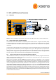
Sampling ADC Physical Calibratio n Sensor Fusion Output Data Triggering Hardware trigger only Hardware/ software triggers When the MTi / MTx is in Measurement State, the internal DSP continuously runs a loop roughly according to the above diagram. The triggering can be generated by device internal sampling triggers, or by external software triggers (polling), or even hardware triggers (normally not recommended). For more information about triggering see section 5.5.
The Preamble, BusID, MesssageID, length indicator and checksum together is always 5 bytes. The length of the various data messages is discussed in [LLCP]. Example 1: Calibrated data output mode at 100 Hz with a baud rate of 115200 bps. Calibrated data is 36 bytes. transmissi on _ time = (36 + 5) * 10bits / byte = 3.56 ms 115200(bits / s ) Together with the internal acquisition and computation time (1.
5.5 Triggering & synchronization In case multiple systems are used during a measurement it is important to have the measurement data synchronized between the systems. Processing synchronised data is much easier because there is no need to resample the data to compensate for timing inaccuracies like clock drift and clock deviations. Synchronization using multiple systems involves 2 important issues: starting the measurement at the same time and having a fixed time relationship of the sampling instances.
Trigger the sampling of the internal sensors In this SyncIn mode the external signal connected to the SyncIn line of the MTi / MTx starts the sampling (AD conversion) of the sensor signals, i.e. accelerations, rate‐of‐turn, magnetic field and temperature. Next, depending on the OutputMode, the physical calibration and the sensor fusion (XKF) are started. If all data is processed it will be transmitted at a rate depending on the OutputSkipFactor (see MTi and MTx Low‐Level Communication Document).
5.6 Internal clock accuracy The internal clock jitter of the MTi and MTx is less than 25ns. The internal clock of the MTi and MTx which generates the sample timing based on the set sample period is accurate to ±30 ppm over the temperature operating range. In practice this means that the worst case deviation after a 1 hour log is ± 0.108 seconds (= 3600 s ∙ 30 ppm) or 10 sample counts in 360,000 at 100 Hz sample rate (± 0.3 μs/sample @ 100 Hz).
6 Physical Specifications 6.1 Physical sensor overview MTi and MTx Sensor Fact Table Accelerometers MEMS solid state, capacitative readout Rate of turn sensor (rate gyroscope) MEMS solid state, monolithic, beam structure, capacitative readout Magnetometer Thin film magnetoresistive Further, the MTi and MTx have several onboard temperature sensors to allow compensation for temperature dependency of the various sensors. © Xsens Technologies B.V. 35 Document MT0100P.
6.2 6.2.1 Physical properties overview MTi overview Communication interface: Additional interfaces: Operating voltage 22 : Power consumption 23 : (AHRS/3D orientation mode) Temperature Operating Range: Specified performance Operating Range: Outline Dimensions: Weight: 6.2.2 MTi‐48A##G## Serial digital (RS‐485) SyncIn SyncOut MTi‐68A##G## Serial digital (RS‐422) SyncIn 4.5‐30 V 4.
6.3 Power supply The nominal power supply of the MTi and MTx is 5V DC. The minimum operating supply voltage is >4.5V and the absolute maximum is <30V. • • • • 6.4 6.4.1 The sensor works at a power supply of >4.5‐30V 24 . Use only SELV (Separated or Safety extra‐low voltage) power supplies (double isolated) that are short‐circuit proof. The average operating power consumption is 350mW (~70 mA @ 5V) for the MTi and MTx. The average power consumption may vary slightly with usage mode (DSP load).
The USB‐serial data and power cable delivered with the MTi and MTx Development Kit is compatible with USB 1.1 and higher. Make sure your PC USB outlet is rated to deliver 100 mA or more (all USB compliant outlets should be). The RS‐422 MTi cable (CA‐USB6) is compatible with the RS‐422 version of the MTi. Blue cable markers are located at the connector and the casing for visual distinction between the RS‐232 MTi cable.
Pin 3 Pin 4 Pin 5 Pin 6 Pin 7 Reserved TX (sensor) RX (sensor) Reserved SyncIn Z/B Y/A Reserved Reserved Reserved For definition of wire colors see next sections. The operating temperature of the USB‐serial data and power cable (CA‐USB) is 0 °C ‐ 40°C. The MTi and MTx are designed to be used with the power supply supplied by Xsens (integrated in the RS‐ 232/422/485 to USB cable). It is possible to use other power supplies; however this must be done with care.
6.4.
Reserved SyncOut SyncIn Pin 5 Pin 6 Pin 7 ODU pin Unitronic cable Yellow Yellow‐green Black Beige Brown Green Blue Pin 1 Pin 2 Pin 3 Pin 4 Pin 5 Pin 6 Pin 7 6.4.
TX‐ / B1 (sensor) RX+ / A2 (sensor) RX‐ / B2 (sensor) SyncIn Pin 4 Pin 5 Pin 6 Pin 7 ODU pin Unitronic cable Yellow Yellow‐green Black Beige Brown Green Blue Pin 1 Pin 2 Pin 3 Pin 4 Pin 5 Pin 6 Pin 7 6.4.
VCC GND TX (sensor) RX (sensor) SyncIn 6.4.
6.4.
6.4.8 Additional interface specifications The MTi & MTx has additional interface lines for synchronization and/or analog input support. Which features are supported depends on the type of device. See pin definitions of the device. Analog IN This line supports in 16 bit sampling of an external analog signal of voltage range 0 to 5V at the sampling frequency used by the MTi / MTx. A data field is added to the data message which contains the 16‐bit representation of the analog voltage.
The signal specifications are listed in the next table. Specification Output high voltage Output low voltage Minimum ohmic value of load Latency (offset = 0) Latency (offset > 0) Jitter Value 3.0‐3.3V 0.0V 10 kOhm ‐1.1us +5.4us 40ns Supported by MTi RS‐232 (MTi‐28A##G##) 6.5 Housing mechanical specifications The plastic parts of the housing are made of polyamide (PA6.6). The MTi bottom plate is made of anodized aluminum (6082). The housing is dust‐proof but not water‐proof.
6.5.2 Dimensions MTi © Xsens Technologies B.V. 47 Document MT0100P.
6.5.3 Dimensions MTx © Xsens Technologies B.V. 48 Document MT0100P.
6.6 Physical location of Origin The MTi and MTx is primarily an orientation sensor and as such it is not important where its internal origin is situated, i.e. the orientation is the same for all positions of the MT as it can be considered a rigid body. However, for applications where accelerations are measured it is important to know the true Origin of the MT, which is defined by the physical location of the accelerometer 26 .
6.6.2 MTx © Xsens Technologies B.V. 50 Document MT0100P.
7 Operating Guidelines 7.1 Normal operating procedure NOTE: Please also refer to the Quick Setup Sheet that came in your Development Kit package. 1. 2. 3. 4. 5. 6. 7.2 7.2.
amount of disturbance. Errors in yaw/heading due to such distortions can be quite large, since the earth magnetic field is very weak in comparison to the magnitude of many sources of distortion. Whether or not an object is ferromagnetic should preferably be checked by using the MTi’s or MTx’s magnetometers. It can also be checked with a small magnet, but be careful, you can easily magnetize hard ferromagnetic materials, causing even larger errors.
The MTi and MTx hardware must be kept dry at all times. Condense may damage the internal electronics. The MTi and MTx hardware should be protected from electro static discharges or sources of radiation, as exposure to such source will damage the internal electronics. The MTi and MTx hardware should be protected from violent handling such as drops on hard surfaces. Excessive shocks or violent handling may damage the motion sensors. The MTi and MTx hardware should be protected from strong vibrations.
8.4 Absolute maximum ratings Stresses above Absolute Maximum Ratings may cause permanent damage to the device. Shock (any axis): Input Voltage: Interface inputs: Analog IN: Sync IN: Operating Temperature: Storage Temperature: Humidity: 20000 m/s2 (2000 g) 0.5 ms (half‐sine) ‐0.3 V … 30 V 29 ‐25 V … 25 V (RX, A and B inputs) ‐0.3 V … 5.3 V or 30 mA, whichever comes first ‐0.
NOTE: Xsens reserves the right to make changes in its products in order to improve design, performance, or reliability. Subject to the conditions and limitations on liability stated herein, Xsens warrants that the Product as so delivered shall materially conform to Xsens’ then current specifications for the Product, for a period of one year from the date of delivery.
8.
8.
8.
8.
8.11 Customer Support Xsens Technologies B.V. is glad to help you with any questions you may have about the MTi or MTx, or about the use of the technology for your application. Please contact Xsens Customer Support: Î by e‐mail: support@xsens.com Î telephone: +31(0)88‐9736700 To be able to help you, please mention your Motion Tracker Device ID (on the back of the device) and software license registration number in your e‐mail. © Xsens Technologies B.V. 60 Document MT0100P.