
User manual

DocumentMT0100P.N
©XsensTechnologiesB.V. MTiandMTxUserManualandTechnicalDocumentation
33
Triggerthesamplingoftheinternalsensors
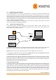
InthisSyncInmodetheexternalsignalconnectedtotheSyncInlineoftheMTi/MTxstartsthesampling(AD
conversion) of the sensor signals, i.e. accelerations, rate‐of‐turn, magnetic field and temperature. Next,
dependingontheOutputMode,thephysicalcalibrationandthe sensorfusion(XKF)arestarted.Ifalldatais
processed it will be transmitted at a rate depending on the OutputSkipFactor (see MTi and MTx Low‐Level
CommunicationDocument).
InthisSyncInmodeitisimportanttosettheMTi/MTxsamplefrequencytothesamefrequencyasthetrigger
signal.FurthermorethetriggersignalshouldhaveatleastthesameaccuracyastheinternalclockoftheMTi/
MTx(seesection5.6).Thisisbecausethestoredsamplefrequencyisusedinthesensorfusioncalculationsand
isnotcorrectedbydeviationsinthetriggersignal.Iftheaccuracyisnothighenoughorthesamplefrequency
cannotbeaccuratelymatchedyoumustchoosethefirstSyncInmode(transmissionoflatestdata).Moreover,
asamplefrequencybelow100HzisnotsupportedbytheMTi/MTxsinceitwouldcompromisetotalaccuracy,
so the trigger frequency must be at least 100 Hz. Note that the output frequencies lower than 100 Hz are
supported.
5.5.2 MTi/MTxtriggersexternaldevices
IncasetheclockspecificationoftheMTi/MTxisaccurateenoughforthemeasurement,theMTi/MTxcan
provide a sync pulse which is generated based on its internal clock. For more details on clock accuracy see
section 5.6. The sync pulse or SyncOut signal will mark the time instance at which the MTi /MTx starts
samplingtheinternalsensors
20
andcontinuedoingthiswhiletheMTi/MTxisinmeasurementstateandwith
thefrequencyrelatedtothecurrentsamplefrequency.Thesignalcanbesettoeitherpulseortogglemode
andincaseofpulsemodethepolaritycanbesettonegativeorpositive.Formoreinformationaboutenabling
SyncOutanditssettingsseeMTiandMTxLow‐LevelCommunicationDocument.
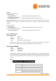
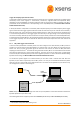
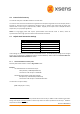
To connect the SyncOut signal to an external device you can either make a custom cable that wires the
SyncOutpin(seesection6.4)directlyfromtheMTi/MTxorin caseyouusetheUSB‐serialdataandpower
cableyoucanuseaspareheaderintheUSBconverterforaconnectiontotheSyncOutline(seesection6.4.1).
Thisconfigurationisshowninthenextfigure.
NOTE:Alwayscheck iftheinput voltage levelsandtheinput impedanceof the externaldevicematches the
SyncOutspecifications(seesection6.4).
ThefollowingMTidevicessupportSyncOut:MTi‐28A##G##(MTiRS‐232)andMTi‐48A##G##(MTiRS‐485).
20
ProvidedthattheSyncOutoffsetsettingiszero.
MT
USB
Converter
Trigger Input
External
device
S
y
ncOu
t