Dahua HD IR Panoramic Bullet Network Camera Quick Start Guide Version 1.0.1 Dahua Vision Technology Co.
Welcome Thank you for purchasing our Network camera! This user’s manual is designed to be a reference tool for your system. Please read the following safeguard and warnings carefully before you use this series product! Please keep this user’s manual well for future reference! Important Safeguards and Warnings 1.Electrical safety All installation and operation here should conform to your local electrical safety codes. Please check if the power supply is correct before operating the device.
. Operation and Daily Maintenance Please do not touch the heat dissipation component of the device directly in order to avoid scald. Please do not dismantle the device; there is no component which can be fixed by users themselves in the machine. It may cause water leakage or bad image for the device due to unprofessional dismantling. Please contact after-sale service to replace desiccant if it becomes green.
Please contact the customer service for the latest procedure and supplementary documentation. There may be deviation between the actual value of some data and the value provided in the manual due to the reasons such as the real environment is not stable and so on. Please refer to the company’s final explanation if there is any doubt or dispute. The company is not liable for any loss caused by the operation which is not followed by the manual. FCC Information 1.
Table of Contents 1 Device Structure ......................................................................................................................... 1 1.1 Device External Cable ................................................................................................. 1 1.2 Framework and Dimension ......................................................................................... 2 1.3 Alarm Setup....................................................................................
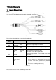
1 Device Structure 1.1 Device External Cable Note: The following figure is for reference only, which is used to know the function of cable port. You can refer to the following figure for cable information. See Figure 1-1. Figure 1-1 Please refer to the following sheet for detailed information. No. Port Name Function 1 AUDIO OUT 2 3 4 Connector Note Audio output port RCA Output audio signal to speaker and etc.
Port Name I/O Port SN Name Note 1 ALARM_OUT 2 ALARM_OUT_GND Alarm output port. It is to output the alarm signal to the alarm device. 3 ALARM_IN1 Alarm input port 1. It is to receive the on-off signal from the external alarm source. 4 ALARM_IN2 Alarm input port 2. It is to receive the on-off signal from the external alarm source. 5 ALARM_IN_GND Alarm input ground port Sheet 1-2 1.
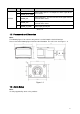
Figure 1-3 Alarm input, output connection description: Step 1 Connect alarm input device to the alarm input of I/O port cable. Step 2 Connect alarm output device to the ALARM_OUT and ALARM_OUT_GND of I/O port cable, Alarm output is the relay switch output; alarm output port can only be connected to NO (normally open) alarm device. Step 3 Open the WEB, set alarm input and output correspondingly in alarm setup. Alarm input on the WEB is corresponding to that of the device I/O port cable.
Alarm output: port ALARM_OUT and ALM_OUT_GND form a switch, which is used to provide alarm output. Normally the switch is on; it will be off when there is alarm output.
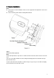
2 Device Installation Note: Please make sure the installation surface can min support the 3X weight of the camera and the bracket. Please cut off the power before installing Micro SD card. Figure 2-1 Step 1 SD card installation (Optional) Note: It needs to implement the step if there is a SD card slot in the device and it needs to use the SD card. You can see the SD installation card slot, analog video output port and reset button after you open the lower cover.
Figure 2-2 Note: You can connect the analog output port to the TV monitor to check image via analog output cable. Press the reset button for 4 to 5 seconds to realize reset function for the device. Step 2 Stick the installation position map on the designated surface where you will install the device (wall or ceiling), then dig holes according to hole location marked on installation map. Step 3 Open the accessories bag, take out expansion bolts and insert them into the hole you just dug.
Figure 2-3 1. Use screwdriver to loosen adjusting screws. 2. Adjust the device in all possible directions, and set its monitoring direction according to use requirement. 3. Use screwdriver to tighten the adjusting screws. Step 7 Waterproof connector installation for network port; see Figure 2-4 for more details. Note: Please implement this step if the device is equipped with network port waterproof connector and it is used outdoors. Figure 2-4 1.
4. Put the waterproof locking cover on the main body of waterproof connector and rotate it clockwise to lock the waterproof connector and waterproof locking cover firmly.
3 Network Configuration The IP address of all the cameras is the same when leaving factory (default IP192.168.1.108), in order to make the camera get access to the network smoothly, please plan the useable IP segment reasonably according to the actual network environment. 3.
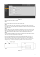
See Figure 3-2 for more details. Figure 3-2 3.2 Login WEB Interface Note: Different devices may have different WEB interfaces, the figures below are just for reference, please refer to the document <> in the disk and the actual interface for more details Step 1 Open IE and input the modified camera IP address in the address bar.
Figure 3-3 Step 3 Install controls according to the system prompt; see Figure 3-4 for the WEB main interface. Please modify the administrator password as soon as possible after you successfully logged in.
Note: This quick start guide is for reference only. Slight difference may be found in user interface. All the designs and software here are subject to change without prior written notice. If there is any uncertainty or controversy, please refer to the final explanation of us. Please visit our website or contact your local service engineer for more information. Dahua Vision Technology Co., Ltd Address:No.1199 Bin’an Road, Binjiang District, Hangzhou, PRC.