
Quick Start Guide


3
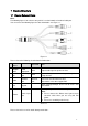
Figure 1-3
Alarm input, output connection description:
Step 1
Connect alarm input device to the alarm input of I/O port cable.
Step 2
Connect alarm output device to the ALARM_OUT and ALARM_OUT_GND of I/O port cable,
Alarm output is the relay switch output; alarm output port can only be connected to NO (normally
open) alarm device.
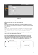
Step 3
Open the WEB, set alarm input and output correspondingly in alarm setup. Alarm input on the
WEB is corresponding to that of the device I/O port cable. When there is alarm, alarm input
device will generate signal of high and low level. Set corresponding NO and NC inputs.
Step 4
Set alarm output on the WEB, the alarm output is corresponding to the alarm output end of the
device, this is the alarm output port of the I/O port cable.
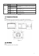
Please refer to the following figure for alarm input and output information. See Figure 1-4.
Alarm input: When the input signal is idle or grounded, the device can collect the different
statuses of the alarm input port. The input signal is connected to 3.3V or it is idle; the device
collects the logic “1”. When the input signal is grounded, the device collects the logic “0”.
Figure 1-4