
Daikin AHKD Installation Manual

2
ONLY
INDIVIDUALS
MEETING
THE
REQUIREMENTS
OF
AN
“E
NTRY
L
EVEL
T
ECHNICIAN
”,
AT
A
MINIMUM
,
AS
SPECIFIED
BY
THE
A
IR
C
ONDITIONING
, H
EATING
AND
R
EFRIGERATION
I
NSTITUTE
(AHRI)
MAY
USE
THIS
INFORMATION
. A
TTEMPTING
TO
INSTALL
OR
REPAIR
THIS
UNIT
WITHOUT
SUCH
BACKGROUND
MAY
RESULT
IN
PRODUCT
DAMAGE
,
PERSONAL
INJURY
,
OR
DEATH
.
WARNING
T
O
AVOID
PROPERTY
DAMAGE
,
PERSONAL
INJURY
OR
DEATH
DUE
TO
ELECTRICAL
SHOCK
,
THIS
UNIT
MUST
HAVE
AN
,
ELECTRICAL
GROUND
. T
HE
ELECTRICAL
GROUND
CIRCUIT
MAY
CONSIST
OF
AN
APPROPRIATELY
SIZED
ELECTRICAL
WIRE
CONNECTING
THE
GROUND
LUG
IN
THE
UNIT
CONTROL
BOX
TO
THE
BUILDING
ELECTRICAL
SERVICE
PANEL
.
O
THER
METHODS
OF
GROUNDING
ARE
PERMITTED
IF
PERFORMED
IN
ACCORDANCE
WITH
THE
N
ATIONAL
E
LECTRIC
C
ODE
(NEC)/A
MERICAN
N
ATIONAL
S
TANDARDS
I
NSTITUTE
(ANSI)/N
ATIONAL
F
IRE
P
ROTECTION
A
SSOCIATION
(NFPA) 70
AND
LOCAL
/
STATE
CODES
. I
N
C
ANADA
,
ELECTRICAL
GROUNDING
IS
TO
BE
IN
ACCORDANCE
WITH
THE
C
ANADIAN
E
LECTRIC
C
ODE
(CSA) C22.1.
UNINTERRUPTED
UNBROKEN
WARNING
W
HEN
INSTALLING
OR
SERVICING
THIS
EQUIPMENT
,
SAFETY
CLOTHING
,
INCLUDING
HAND
AND
EYE
PROTECTION
,
IS
STRONGLY
RECOMMENDED
.
I
F
INSTALLING
IN
AN
AREA
THAT
HAS
SPECIAL
SAFETY
REQUIREMENTS
(
HARD
HATS
,
ETC
.), O
BSERVE
THESE
REQUIREMENTS
.
CAUTION
D
O
NOT
CONNECT
TO
OR
USE
ANY
DEVICE
THAT
IS
NOT
DESIGNED
CERTIFIED
BY
D
AIKIN
FOR
USE
WITH
THIS
UNIT
. S
ERIOUS
PROPERTY
DAMAGE
,
PERSONAL
INJURY
,
REDUCED
UNIT
PERFORMANCE
AND
/
OR
HAZARDOUS
CONDITIONS
MAY
RESULT
FROM
THE
USE
OF
SUCH
NON
-
APPROVED
DEVICES
.
WARNING
C
ODES
& R
EGULATIONS
This product is designed and manufactured to comply with na-
tional codes. Installation in accordance with such codes and/or
prevailing local codes/regulations is the responsibility of the in-
staller. The manufacturer assumes no responsibility for equip-
ment installed in violation of any codes or regulations.
P
RE
-I
NSTALLATION
I
NSTRUCTIONS
Carefully read all instructions for the installation prior to install-
ing product. Make sure each step or procedure is understood
and any special considerations are taken into account before
starting installation. Assemble all tools, hardware and supplies
needed to complete the installation. Some items may need to
be purchased locally. Make sure everything needed to install the
product is on hand before starting.
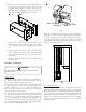
M
ODEL
I
DENTIFICATION
Refer to this manual in combination with the instructions provided
with the air handler for the correct installation procedure.
The electrical characteristics of the air handler, the electric heat
kit and the building power supply must agree.
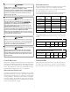
Use the following table and the product’s Series and Rating Plate
to determine the heating kW and electrical characteristics.
Nominal
kW
AHKD15-3 15 208-230/3/60 1
AHKD15-4 15 460/3/60 1
AHKD20-3 20 208-230/3/60 2
AHKD20-4 20 460/3/60 2
AHKD30-3 30 208-230/3/60 2
AHKD30-4 30 460/3/60 2
AHKD Model
Number
Electrical
Characteristics
Stages
Table 1.
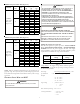
For all supply voltages, use the correction factors in Tables 2 & 3,
multiplied by kW and (or) temperature rise to have corrected
results.
Supply Voltage 240 230 220 210 208
Correction Factor 1.0 0.92 0.84 0.77 0.75
KW Correction Factors (-3 models)
Table 2.
Supply Voltage 480 460 440 415 380
Correction Factor 1.0 0.92 0.84 0.75 0.63
KW Correction Factors (-4 models)
Table 3.
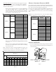
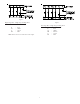
T
EMPERATURE
R
ISE
The heating mode temperature rise is dependent upon the sys-
tem airflow, the supply voltage, and the heat kit size (kW) se-
lected. Use Tables 4 & 5 to determine the temperature rise (
o
F):