
Daikin AHKD Installation Manual

4
Determine Wire Size The selection of the appropriate supply
wire size is important to the operation of the equipment.
When selecting the wire size, the following are important
elements of the decision:
· The wire size is adequately sized to carry the Minimum Cir-
cuit Ampacity (MCA). Refer to the NEC (USA) or CSA
(Canada) for wire sizing. The unit MCA for the air handler
and the optional electric heat kit can be found on the equip-
ment S&R plate and the following table.
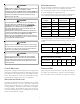
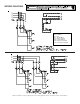
AIRHANDLER VOLTAGE HEAT KIT MCA
None 6.5
AHKD15-3 49.8
AHKD20-3 64.2
AHKD30-3 93.1
None 3.3
AHKD15-4 24.9
AHKD20-4 32.1
AHKD30-4 46.6
None 9.8
AHKD15-3 53.1
AHKD20-3 67.5
AHKD30-3 96.4
None 4.9
AHKD15-4 26.5
AHKD20-4 33.7
AHKD30-4 48.2
DAR0904
208-230
460
DAR1204
208-230
460
Table 7.
· The wire size is appropriately sized to allow for no more
than a 2% voltage drop from the building breaker/fuse panel
to the unit.
· Refer to the latest edition of the National Electric Code or
in Canada the Canadian Electric Code when determining
the correct wire size.
Table 8 shows the current carrying capabilities for copper con-
ductors rated at 75
o
C with a 2% voltage drop. Use Table 8 to de-
termine the voltage drop per foot of various conductors.
Wire
Size
(AWG)1015202530354045
14 75 50 37 NR NR NR NR NR
12118795947NRNRNRNR
10 188 125 95 75 63 54 NR NR
8 301 201 150 120 100 86 75 68
6 471 314 235 188 157 134 118 110
Based on NEC 1996
Max. Allowable Length in Feet to Limit Voltage
Drop to 2%
Min. Circuit Ampacity (MCA)
Table 8.
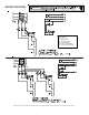
M
AXIMUM
O
VERCORRECT
P
ROTECTION
(MOP)
Every installation must include an NEC (USA) or CEC (Canada) ap-
proved overcorrect protection device. Also, check with local or
state codes for any special regional requirements.
Protection can be in the form of fusing or HACR style circuit break-
ers. The Series and Rating Plate can be used as a guide for select-
ing the MAXIMUM overcurrent device or reference the following
table.
NOTE: Fuses or circuit breakers are to be sized larger than the
equipment MCA but not to exceed the MOP.
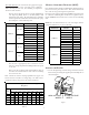
AIRHANDLER HEAT KIT MOP
None 15
AHKD15-3 50
AHKD20-3 70
AHKD30-3 100
None 15
AHKD15-4 25
AHKD20-4 35
AHKD30-4 50
None 15
AHKD15-3 60
AHKD20-3 70
AHKD30-3 100
None 15
AHKD15-4 30
AHKD20-4 35
AHKD30-4 50
DAR0904
DAR1204
Table 9.
A
TTACHING
THE
H
EAT
K
IT
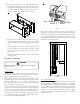
1. Secure the high voltage and low voltage conduits to the heat
kit electrical panel using the supplied plastic bushing nuts as
shown in Figure 1.
LOW VOLTAGE
WIRES
HIGH VOLTAGE
WIRES
Figure 1.