
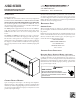
Daikin AHKD Installation Manual

5
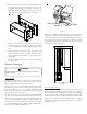
2. The heat kit attaches directly to the top panel (when viewed
in the upflow position) of the air handler. Do not screw the
heat kit into the duct flanges. Position the heat kit onto the
air handler at the air discharge end with the control box
orientated toward the airhandler front. See Figure 2.
Figure 2.
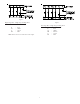
3. Route the two electrical conduits (attached in step 1.)
through the panel on the airhandler. Secure the conduits
to the air handler panel with the supplied plastic bushing
nuts.
4. Using the supplied ½” long #10 screws, attach the heat kit
to the air handler outlet panel. Note: Open the heat kit
electrical panel door to obtain access to the three screws
on that side.
5. Follow the “Electrical Connections” section of this manual
for wiring details.
E
LECTRICAL
C
ONNECTIONS
T
O
AVOID
THE
RISK
OF
FIRE
OR
EQUIPMENT
DAMAGE
,
USE
COPPER
CONDUCTORS
ONLY
.
WARNING
Supply Voltage
A single point supply voltage termination is provided in the heat
kit control box. The wire is to be sized in accordance with the
Electrical Wire and MOP section of this manual.
The supply wire is to be routed through conduit from the service
disconnect box to the heater kit. The heat kit is equipped with a
knockout suitable for 1/2” or 3/4” conduit., dependent on the
kW. The supply voltage is to be installed on the terminal block
located in the heater kit control box.
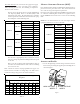
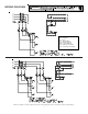
The heater kit is factory equipped with the supply and low volt-
age wires for the air handler. The low voltage connection from
the heater kit is provided through a multi-pin plug which con-
nects to a mating plug in the air handler. The high voltage con-
nections are to be made at the air handler contactor. These wires
are to be routed through the pipe nipples supplied with the heater
kit as shown in the following illustration.
LOW VOLTAGE
WIRES
HIGH VOLTAGE
WIRES
Figure 3.
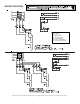
Route the air handler supply voltage and ground conductors
though the ½” conduit that connects the heat kit to the airhandler.
Attach the supply voltage wires to the airhandler contactor and
the equipment ground to the airhandler ground lug. To assist
with possible troubleshooting, follow the wire color conventions
indicated on the wiring diagram.
Figure 4.
Low Voltage Connections
The low voltage connection from the air handler to the heat kit is
provided through a multi-pin plug that connects to a mating plug
in the airhandler. Route the heat kit low voltage harness through
the 1 ½” conduit to the airhandler control box and plug into the
airhandler low voltage harness. Note: Low voltage from the room
thermostat is terminated in the airhandler control box. Wiring
options for the thermostat wiring are shown in the air handler
installation manual.