
Daikin DP14CM Installation Manual


7
HIGH VOLTAGE WIRING
• Single Phase- Two leads should be connected to terminals L1 &
L2 in the electrical control section, using wire sizes specified in
wiring table.
• Three Phase- Three leads should be connected to terminals L1,
L2 and L3 in the electrical control section, using wire sizes
specified in wiring table.
LOW VOLTAGE WIRING
• Air Conditioners- Connect 24V wires from the thermostat to the
corresponding wires in the control box using No. 18 AWG as
follows:
LEAD THERMOSTAT
Red R (24V)
Green G (Fan)
Yellow Y (Cool)
White W1 (Heat)*
Brown W2 (Heat)*
Blue C (Common)
• Heat Pumps- Connect 24V wires from the thermostat to the
corresponding wires in the control box using No. 18 AWG as
follows:
TERMINAL THERMOSTAT
Red R (24V)
Green G (Fan)
Orange 0 (Rev. Valve)
White W1 (Heat, 2nd)*
Brown W2 (Heat, 3rd)*
Yellow Y (Cool)
Blue C (Common)
*Optional field installed heat connections
INTERNAL WIRING
A diagram detailing the internal wiring of this unit is located on the elec-
trical box cover. If any of the original wire supplied with the appliance
must be replaced, the wire gauge and insulation must be the same as the
original wiring.
Transformer is wired for 230 volts on the 208/230 models. See wiring dia-
gram for 208 volt wiring.
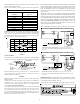
1. For branch circuit wiring (main power supply to unit disconnect),
the minimum wire size for the length of run can be determined
using the circuit ampacity found on the unit rating plate and the
table below. From the unit disconnect to unit, the smallest wire
size allowable may be used for the ampacity, as the Disconnect
must be in sight of the unit.
BRANCH
CIRCUIT AMPACITY
15 20 25 30 35 40 45 50
SUPPLY WIRE LENGTH
(FEET)
200 64443322
150 86644433
100 108866644
50 14 12 10 10 8 8 6 6
2. Wire size based on 60° C rated wire insulation and 30° C Ambient
Temperature (86° F).
3. For more than 3 conductors in a raceway or cable, see the N.E.C.
for derating the ampacity of each conductor.
STARTUP, ADJUSTMENTS, AND CHECKS
WARNING
HIGH VOLTAGE!
DISCONNECT ALL POWER BEFORE SERVICING OR INSTALLING
THIS UNIT.
MULTIPLE POWER SOURCES MAY BE PRESENT. FAILURE
TO DO SO MAY CAUSE PROPERTY DAMAGE, PERSONAL INJURY OR
DEATH.
START-UP PROCEDURE AND CHECKLIST
With power turned off at all disconnects:
1. Turn thermostat system switch to “COOL” and fan switch to
“AUTO”. Next, turn the temperature setting as high as it
will go.
2. Inspect all registers and set them to the normal open
position.
3. Turn on the electrical supply at the disconnect.
4. Turn the fan switch to the “ON” position. The blower should
operate after a 7-second delay (10 seconds for models
with EEM motors).
5. Turn the fan switch to “AUTO” position. The blower should
stop after a 65-second delay (60 seconds for models with
EEM motors).
6. Slowly lower the cooling temperature until the unit starts.
The compressor, blower and fan should now be operating.
Allow the unit to run 10 minutes, make sure cool air is
being supplied by the unit.
7. Turn the temperature setting to the highest position,
stopping the unit. The indoor blower will continue to run
for 65-seconds (60 seconds for models with EEM motors).
8. Turn the thermostat system switch to “OFF” and disconnect all
power when servicing the unit.
HEAT PUMP START-UP PROCEDURE
1. Check the cooling mode for the heat pump in the same manner
as above. The reversing valve is energized when the thermostat
is placed in the cooling position. A clicking sound should be
noticeable from the reversing valve. By lowering the
temperature setting to call for cooling, the contactor is energized.
The compressor, blower and fan should then be running. After
the cooling mode is checked out, turn the thermostat system
switch to “OFF”.
2. Turn the thermostat system switch to “HEAT” and fan switch to
“AU TO”.