SiUS281811E Service Manual RZR-TA, RZQ-TA Series Cooling Only 60 Hz Heat Pump 60 Hz
SiUS281811E Introduction ....................................................................................... 1 1. Safety Cautions...........................................................................................2 1.1 Warnings and Cautions Regarding Safety of Workers................................. 2 1.2 Warnings and Cautions Regarding Safety of Users..................................... 4 2. Icons Used ..........................................................................................
SiUS281811E Part 4 Functions and Control .......................................................... 72 1. Operation Mode ........................................................................................73 2. Basic Control.............................................................................................74 2.1 2.2 2.3 2.4 Normal Operation ....................................................................................... 74 Compressor PI Control.........................................
SiUS281811E 2.2 2.3 2.4 2.5 2.6 2.7 2.8 2.9 2.10 2.11 Setting Mode and Monitor Mode .............................................................. 139 Setting Mode 1 ......................................................................................... 140 Setting Mode 2 ......................................................................................... 142 Monitor Mode ...........................................................................................
SiUS281811E 4.17 4.18 4.19 4.20 4.21 4.22 4.23 4.24 4.25 4.26 4.27 4.28 4.29 4.30 4.31 4.32 4.33 4.34 4.35 4.36 4.37 4.38 4.39 4.40 4.41 4.42 4.43 4.44 4.45 4.46 4.47 4.48 4.49 4.50 4.51 4.52 4.53 4.54 4.55 4.56 4.57 4.58 4.59 Drain Level Above Limit ........................................................................... 205 Capacity Determination Device Abnormality ............................................ 206 Transmission Abnormality (between Indoor Unit PCB and Fan PCB) .....
SiUS281811E 5.3 5.4 5.5 5.6 5.7 5.8 5.9 5.10 5.11 5.12 5.13 5.14 5.15 Superheat Operation Check..................................................................... 263 Power Transistor Check ........................................................................... 264 Refrigerant Overcharge Check................................................................. 265 Refrigerant Shortage Check..................................................................... 266 Vacuuming and Dehydration Procedure ....
SiUS281811E Introduction 1. Safety Cautions...........................................................................................2 1.1 Warnings and Cautions Regarding Safety of Workers................................. 2 1.2 Warnings and Cautions Regarding Safety of Users..................................... 4 2. Icons Used ..................................................................................................7 3. Revision History ...........................................................
Safety Cautions SiUS281811E 1. Safety Cautions Be sure to read the following safety cautions before conducting repair work. After the repair work is complete, be sure to conduct a test operation to ensure that the equipment operates normally, and explain the cautions for operating the product to the customer. This manual is for the person in charge of maintenance and inspection. Caution Items The caution items are classified into Warning and Caution.
SiUS281811E Safety Cautions Warning Be sure to discharge the capacitor completely before conducting repair work. The step-up capacitor supplies high-voltage electricity to the electrical components of the outdoor unit. A charged capacitor may cause an electrical shock. Do not turn the air conditioner on or off by plugging in or unplugging the power cable. Plugging in or unplugging the power cable to operate the equipment may cause an electrical shock or fire.
Safety Cautions SiUS281811E Caution Be sure to check that the refrigerating cycle section has cooled down enough before conducting repair work. Working on the unit when the refrigerating cycle section is hot may cause burns. Conduct welding work in a well-ventilated place. Using the welder in an enclosed room may cause oxygen deficiency. 1.2 Warnings and Cautions Regarding Safety of Users Warning Do not store the equipment in a room with fire sources (e.g.
SiUS281811E Safety Cautions Warning Do not mix air or gas other than the specified refrigerant (R-410A) in the refrigerant system. If air enters the refrigerant system, an excessively high pressure results, causing equipment damage and injury. If the refrigerant gas leaks, be sure to locate the leaking point and repair it before charging the refrigerant. After charging the refrigerant, make sure that there is no leak.
Safety Cautions SiUS281811E Caution Be sure to measure insulation resistance after the repair, and make sure that the resistance is 1 M or greater. Faulty insulation may cause an electrical shock. Be sure to check the drainage of the indoor unit after the repair. Faulty drainage may cause water to enter the room and wet the furniture and floor. Do not tilt the unit when removing it. The water inside the unit may spill and wet the furniture and floor.
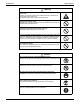
SiUS281811E Icons Used 2. Icons Used The following icons are used to attract the attention of the reader to specific information. Icon Warning Caution Note Reference Introduction Type of Description Information Warning Warning is used when there is danger of personal injury. Caution Note Reference Caution is used when there is danger that the reader, through incorrect manipulation, may damage equipment, lose data, get an unexpected result or have to restart (part of) a procedure.
Revision History SiUS281811E 3.
SiUS281811E Part 1 General Information 1. Model Names and Power Supply..............................................................10 1.1 Cooling Only............................................................................................... 10 1.2 Heat Pump ................................................................................................. 11 2. External Appearance.................................................................................12 2.1 Indoor Unit........................
Model Names and Power Supply SiUS281811E 1. Model Names and Power Supply 1.
SiUS281811E 1.
External Appearance SiUS281811E 2. External Appearance 2.
SiUS281811E External Appearance Multi Position Air Handling Unit FTQ18TAVJUD, FTQ18TAVJUA FTQ24TAVJUD, FTQ24TAVJUA FTQ30TAVJUD, FTQ30TAVJUA FTQ36TAVJUD, FTQ36TAVJUA FTQ42TAVJUD, FTQ42TAVJUA FTQ48TAVJUD, FTQ48TAVJUA 2.
External Appearance 2.3 SiUS281811E Remote Controller Wired remote controller BRC1E73 Wireless remote controller BRC7E83 (FHQ) BRC7E818 (FAQ) BRC4C82 (FBQ (1), FTQ) BRC082A43 (FBQ (1)) 1. For FBQ series, the fan step control is different according to the wireless remote controller used.
SiUS281811E Specifications 3. Specifications 3.1 Cooling Only 3.1.
Specifications Model name SiUS281811E Indoor unit Outdoor unit Power supply 1 2 Cooling capacity SEER (Rated) EER (Rated) Indoor unit Casing color Dimensions: (H×W×D) Coil Type Rows×Stages×FPI Face area Fan Model Type Motor output Airflow rate (H/M/L) External static pressure Sound pressure level (H/M/L) Air filter Weight Connecting Liquid Pipe Pipes Gas Pipe Drain Pipe Remote controller Wired (option) Wireless Decoration Model panels Color (option) Dimensions: (H×W×D) Air filter Weight Outdoor unit C
SiUS281811E Model name Specifications Indoor unit Outdoor unit Power supply 1 2 Cooling capacity SEER (Rated) EER (Rated) Indoor unit Casing color Dimensions: (H×W×D) Coil Type Rows×Stages×FPI Face area Fan Model Type Motor output Airflow rate (H/M/L) External static pressure Sound pressure level (H/M/L) Air filter Weight Connecting Liquid Pipe Pipes Gas Pipe Drain Pipe Remote controller Wired (option) Wireless Decoration Model panels Color (option) Dimensions: (H×W×D) Air filter Weight Outdoor unit C
Specifications SiUS281811E 3.1.
SiUS281811E Model name Specifications Indoor unit Outdoor unit Power supply 1 2 Cooling capacity SEER (Rated) EER (Rated) Indoor unit Casing color Dimensions: (H×W×D) Coil Type Rows×Stages×FPI Face area Fan Model Type Motor output Airflow rate (H/L) External static pressure Air filter Weight Connecting Pipes Liquid Pipe Gas Pipe Drain Pipe Remote controller Wired (option) Wireless Outdoor unit Casing color Dimensions: (H×W×D) Coil Type Rows×Stages×FPI Face area Compressor Model Type Motor output Fan
Specifications Model name Indoor unit Outdoor unit Power supply 1 2 Cooling capacity SEER (Rated) EER (Rated) Indoor unit Casing color Dimensions: (H×W×D) Coil Type Rows×Stages×FPI Face area Fan Model Type Motor output Airflow rate (H/L) External static pressure Air filter Weight Connecting Pipes SiUS281811E Liquid Pipe Gas Pipe Drain Pipe Remote controller Wired (option) Wireless Outdoor unit Casing color Dimensions: (H×W×D) Coil Type Rows×Stages×FPI Face area Compressor Model Type Motor output Fan
SiUS281811E Specifications 3.1.
Specifications SiUS281811E 3.1.
SiUS281811E Model name Specifications Indoor unit Outdoor unit Power supply 1 2 Cooling capacity SEER (Rated) EER (Rated) Indoor unit Casing color Dimensions: (H×W×D) Coil Type Rows×Stages×FPI Face area Fan Model Type Motor output Airflow rate (H/M/L) External static pressure Sound pressure level (HH/H/L) Air filter Weight Connecting Liquid Pipe Pipes Gas Pipe Drain Pipe Remote controller Wired (option) Wireless Outdoor unit Casing color Dimensions: (H×W×D) Coil Type Rows×Stages×FPI Face area Compress
Specifications Model name SiUS281811E Indoor unit Outdoor unit Power supply 1 2 Cooling capacity SEER (Rated) EER (Rated) Indoor unit Casing color Dimensions: (H×W×D) Coil Type Rows×Stages×FPI Face area Fan Model Type Motor output Airflow rate (H/M/L) External static pressure Sound pressure level (HH/H/L) Air filter Weight Connecting Liquid Pipe Pipes Gas Pipe Drain Pipe Remote controller Wired (option) Wireless Outdoor unit Casing color Dimensions: (H×W×D) Coil Type Rows×Stages×FPI Face area Compress
SiUS281811E Specifications 3.1.
Specifications Model name SiUS281811E Indoor unit Outdoor unit Power supply 1 2 Cooling capacity SEER (Rated) EER (Rated) Indoor unit Casing color Dimensions: (H×W×D) Coil Type Face area Fan Type Motor output Airflow rate (H/M/L) External static pressure Sound pressure level (H/M/L) Air filter Weight Connecting Liquid Pipe Pipes Gas Pipe Drain Pipe Remote controller Wired (option) Wireless Outdoor unit Casing color Dimensions: (H×W×D) Coil Type Rows×Stages×FPI Face area Compressor Model Type Motor out
SiUS281811E Model name Specifications Indoor unit Outdoor unit Power supply 1 2 Cooling capacity SEER (Rated) EER (Rated) Indoor unit Casing color Dimensions: (H×W×D) Coil Type Face area Fan Type Motor output Airflow rate (H/M/L) External static pressure Sound pressure level (H/M/L) Air filter Weight Connecting Liquid Pipe Pipes Gas Pipe Drain Pipe Remote controller Wired (option) Wireless Outdoor unit Casing color Dimensions: (H×W×D) Coil Type Rows×Stages×FPI Face area Compressor Model Type Motor out
Specifications 3.2 SiUS281811E Heat Pump 3.2.
SiUS281811E Model name Specifications Indoor unit Outdoor unit Power supply 1 4 Cooling capacity 2 4 Heating capacity 3 4 Heating capacity SEER (Rated) EER (Rated) HSPF (Rated) Indoor unit Casing color Dimensions: (H×W×D) Coil Type Rows×Stages×FPI Face area Fan Model Type Motor output Airflow rate (H/M/L) External static pressure Sound pressure level (H/M/L) Air filter Weight Connecting Liquid Pipe Pipes Gas Pipe Drain Pipe Remote controller Wired (option) Wireless Decoration Model panels Color (o
Specifications Model name SiUS281811E Indoor unit Outdoor unit Power supply 1 4 Cooling capacity 2 4 Heating capacity 3 4 Heating capacity SEER (Rated) EER (Rated) HSPF (Rated) Indoor unit Casing color Dimensions: (H×W×D) Coil Type Rows×Stages×FPI Face area Fan Model Type Motor output Airflow rate (H/M/L) External static pressure Sound pressure level (H/M/L) Air filter Weight Connecting Liquid Pipe Pipes Gas Pipe Drain Pipe Remote controller Wired (option) Wireless Decoration Model panels Color (o
SiUS281811E Specifications 3.2.
Specifications Model name SiUS281811E Indoor unit Outdoor unit Power supply 1 4 Cooling capacity 2 4 Heating capacity 3 4 Heating capacity SEER (Rated) EER (Rated) HSPF (Rated) Indoor unit Casing color Dimensions: (H×W×D) Coil Type Rows×Stages×FPI Face area Fan Model Type Motor output Airflow rate (H/L) External static pressure Air filter Weight Connecting Pipes Liquid Pipe Gas Pipe Drain Pipe Remote controller Wired (option) Wireless Outdoor unit Casing color Dimensions: (H×W×D) Coil Type Rows×S
SiUS281811E Model name Specifications Indoor unit Outdoor unit Power supply 1 4 Cooling capacity 2 4 Heating capacity 3 4 Heating capacity SEER (Rated) EER (Rated) HSPF (Rated) Indoor unit Casing color Dimensions: (H×W×D) Coil Type Rows×Stages×FPI Face area Fan Model Type Motor output Airflow rate (H/L) External static pressure Air filter Weight Connecting Pipes Liquid Pipe Gas Pipe Drain Pipe Remote controller Wired (option) Wireless Outdoor unit Casing color Dimensions: (H×W×D) Coil Type Rows×S
Specifications SiUS281811E 3.2.
SiUS281811E Specifications 3.2.
Specifications Model name SiUS281811E Indoor unit Outdoor unit Power supply 1 4 Cooling capacity 2 4 Heating capacity 3 4 Heating capacity SEER (Rated) EER (Rated) HSPF (Rated) Indoor unit Casing color Dimensions: (H×W×D) Coil Type Rows×Stages×FPI Face area Fan Model Type Motor output Airflow rate (HH/H/L) External static pressure Sound pressure level (HH/H/L) Air filter Weight Connecting Liquid Pipe Pipes Gas Pipe Drain Pipe Remote controller Wired (option) Wireless Outdoor unit Casing color Dime
SiUS281811E Model name Specifications Indoor unit Outdoor unit Power supply 1 4 Cooling capacity 2 4 Heating capacity 3 4 Heating capacity SEER (Rated) EER (Rated) HSPF (Rated) Indoor unit Casing color Dimensions: (H×W×D) Coil Type Rows×Stages×FPI Face area Fan Model Type Motor output Airflow rate (HH/H/L) External static pressure Sound pressure level (HH/H/L) Air filter Weight Connecting Liquid Pipe Pipes Gas Pipe Drain Pipe Remote controller Wired (option) Wireless Outdoor unit Casing color Dime
Specifications SiUS281811E 3.2.
SiUS281811E Model name Specifications Indoor unit Outdoor unit Power supply 1 4 Cooling capacity 2 4 Heating capacity 3 4 Heating capacity SEER (Rated) EER (Rated) HSPF (Rated) Indoor unit Casing color Dimensions: (H×W×D) Coil Type Face area Fan Type Motor output Airflow rate (H/M/L) External static pressure Sound pressure level (H/M/L) Air filter Weight Connecting Liquid Pipe Pipes Gas Pipe Drain Pipe Remote controller Wired (option) Wireless Outdoor unit Casing color Dimensions: (H×W×D) Coil Typ
Specifications Model name SiUS281811E Indoor unit Outdoor unit Power supply 1 4 Cooling capacity 2 4 Heating capacity 3 4 Heating capacity SEER (Rated) EER (Rated) HSPF (Rated) Indoor unit Casing color Dimensions: (H×W×D) Coil Type Face area Fan Type Motor output Airflow rate (H/M/L) External static pressure Sound pressure level (H/M/L) Air filter Weight Connecting Liquid Pipe Pipes Gas Pipe Drain Pipe Remote controller Wired (option) Wireless Outdoor unit Casing color Dimensions: (H×W×D) Coil Typ
SiUS281811E Part 2 Refrigerant Circuit 1. Refrigerant Circuit (Piping Diagrams) .......................................................42 1.1 RZR18/24TAVJU, RZQ18/24TAVJU.......................................................... 42 1.2 RZR30/36/42/48TAVJU, RZQ30/36/42/48TAVJU...................................... 44 1.3 Indoor Unit.................................................................................................. 46 2. Functional Parts Layout ................................................
Refrigerant Circuit (Piping Diagrams) SiUS281811E 1. Refrigerant Circuit (Piping Diagrams) 1.1 RZR18/24TAVJU, RZQ18/24TAVJU No. in piping diagram Electric symbol (1) M1C Inverter compressor (2) M1F Inverter fan The fan rotation speed is varied by using inverter. (3) Y1E Electronic expansion valve (Main) While in heating operation, PI control is applied to keep the outlet superheated degree of air heat exchanger constant.
Part 2 Refrigerant Circuit (17) (6) (11) (3) (14) (10) (1) (8) S1NPL (13) (9) (7) S1PH S1NPH (15) (18)* (12) C: 3D082498F ∗ The radiation fin thermistor (18) is located near the electrical component box.
Refrigerant Circuit (Piping Diagrams) 1.2 SiUS281811E RZR30/36/42/48TAVJU, RZQ30/36/42/48TAVJU No. in piping diagram Electric symbol (1) M1C Inverter compressor Compressor is operated in multi-steps according to Te and Tc. (2) M1F M2F Inverter fan The fan rotation speed is varied by using inverter. (3) Y1E Electronic expansion valve (Main) While in heating operation, PI control is applied to keep the outlet superheated degree of air heat exchanger constant.
(17) (4) (16) Part 2 Refrigerant Circuit (15) (13) (7) S1NPL S1PH S1NPH (5) (8) (6) (14) (18)* (11) (2) C: 3D088595A ∗ The radiation fin thermistor (18) is located near the electrical component box.
Refrigerant Circuit (Piping Diagrams) 1.3 SiUS281811E Indoor Unit Symbol No. in piping diagram Name Electronic expansion valve (1) (2) Suction air thermistor Liquid pipe thermistor (3) Gas pipe thermistor (4) Discharge air thermistor (5) FCQ-TA FHQ-P FHQ-M FAQ-TA FBQ-P FTQ-TA Y1E Y1E Y1E R1T R1T R1T(1) R2T R2T R2T Used for gas superheated degree control while in cooling or subcooled degree control while in heating.
SiUS281811E Functional Parts Layout 2. Functional Parts Layout 2.
Functional Parts Layout SiUS281811E Side view Four way valve (Y1S) Thermistor (Outdoor air) (R1T) Thermistor (Suction pipe 1) (R3T) Thermistor (Heat exchanger deicer) (R4T) C: 1P342997N 48 Part 2 Refrigerant Circuit
SiUS281811E 2.
Functional Parts Layout SiUS281811E Side view Thermistor (Subcooling heat exchanger gas pipe) (R6T) Thermistor (Suction pipe 1) (R3T) Thermistor (Outdoor air) (R1T) Electronic expansion valve/coil (Main) (Y1E) Electronic expansion valve/coil (Subcooling) (Y3E) Thermistor (Liquid pipe) (R7T) Thermistor (Heat exchanger deicer) (R4T) C: 1P441643J 50 Part 2 Refrigerant Circuit
SiUS281811E Part 3 Remote Controller 1. Applicable Models .....................................................................................52 2. Names and Functions ...............................................................................53 2.1 Wired Remote Controller............................................................................ 53 2.2 Simplified Remote Controller...................................................................... 56 2.3 Wireless Remote Controller ................
Applicable Models SiUS281811E 1.
SiUS281811E Names and Functions 2. Names and Functions 2.1 Wired Remote Controller 1. Operation mode selector button 11. LCD (with backlight) 4. Up button 5. Down button 6. Right button 7. Left button 9. Operation lamp 8. On/Off button 3. Menu/OK button 10. Cancel button 2. Fan speed control button Functions other than basic operation items (i.e., On/Off, Operation Mode, Fan Speed, and Setpoint) are set from the menu screen.
Names and Functions SiUS281811E 4. Up button Used to raise the setpoint. The item above the current selection will be highlighted. (The highlighted items will be scrolled continuously when the button is continuously pressed.) Used to change the selected item. 5. Down button Used to lower the setpoint. The item below the current selection will be highlighted. (The highlighted items will be scrolled continuously when the button is continuously pressed.) Used to change the selected item. 6.
SiUS281811E Names and Functions Service Check Function Main Menu 1/3 Airflow Direction Individual Airflow Direction Ventilation Schedule Off Timer Celsius / Fahrenheit Setting Main Menu screen • Operation mode changeover • Fan speed control • Menu display • Confirmation of each setting • On • Off • Cancel • Operation lamp Press the Menu/OK button once. Press the Cancel button for 4 seconds or more. Press the Cancel button once.
Names and Functions 2.2 SiUS281811E Simplified Remote Controller 1 6 7 3 4 13 5 H L 9 F 12 BRC2A71 ON/OFF BUTTON Press the button and the system will start. Press the button again and the system will stop. DISPLAY “ CONTROL) 7 OPERATION LAMP (RED) 2 The lamp lights up during operation. Blinks in case of stop due to malfunction. DISPLAY “ CONTROL) 3 8 11 10 1 2 ” (CHANGEOVER UNDER 8 When this display shows, the system is UNDER CENTRALIZED CONTROL.
SiUS281811E 2.3 Names and Functions Wireless Remote Controller 1 3 8 ON OFF ON OFF TEMP H M L H 10 DOWN F 6 M 11 L TIME F UP UP DOWN FAN FAN 4 9 hr. 2 13 RESERVE CANCEL hr. hr. 12 15 14 16 17 TIMER hr.
Names and Functions 1 2 3 SiUS281811E DISPLAY “ ” “ I ” (SIGNAL TRANSMISSION) This lights up when a signal is being transmitted. DISPLAY “ ”“ ”“ ”“ ”“ ” (OPERATION MODE) This display shows the current OPERATION MODE. DISPLAY “ H M L F ” (SET TEMPERATURE) This display shows the set temperature. DISPLAY “ hr. This display shows PROGRAMMED TIME of the system start or stop. 5 DISPLAY “ 6 DISPLAY “ ” “ ” (FAN SPEED) This display shows the set fan speed.
SiUS281811E Main/Sub Setting 3. Main/Sub Setting Main/Sub setting is necessary when 1 indoor unit is controlled by 2 remote controllers. The remote controllers are set at factory to Main, so you have to change one remote controller from Main to Sub. To change a remote controller from Main to Sub, proceed as follows: 3.1 Wired Remote Controller (BRC1E73) 3.1.1 Field Settings The designation of the main and sub remote controllers can be swapped.
Main/Sub Setting Note(s) 3.2 SiUS281811E 1. It is not possible to change the Main/Sub setting from Main to Sub when only one remote controller is connected. 2. When 2 remote controllers are being used, it is not possible to change the setting from Main to Sub if one of the remote controllers is already set as Main. When Wireless Remote Controller is Used Together When using both a wired and a wireless remote controller for 1 indoor unit, the wired controller should be set to Main.
SiUS281811E Address Setting for Wireless Remote Controller 4. Address Setting for Wireless Remote Controller If setting multiple wireless remote controllers to operate in one room, perform address setting for the receiver and the wireless remote controller. (This includes an individual remote controller control using the group operation.) (For the wiring for the group operation, please refer to the installation manual attached to the indoor unit and technical guide.
Address Setting for Wireless Remote Controller SiUS281811E Setting for Wireless Remote Controller The address for the wireless remote controller is set to 1 at the factory. To change the setting, proceed as follows: 1. Press FILTER SIGN RESET button and INSPECTION/TEST button at the same time for 4 seconds to enter field setting mode. (SETTING is indicated on the display.) 2. Press FAN button and select A or b. Each time the button is pressed, the display switches between A and b. 3.
SiUS281811E Address Setting for Wireless Remote Controller Multiple Settings A/b The command such as operation mode or temperature setting by this remote controller will be rejected when the target indoor unit operation is restricted as by an external control such as centralized control.
Centralized Control Group No. Setting SiUS281811E 5. Centralized Control Group No. Setting 5.1 BRC1E73 In order to conduct the centralized remote control using the central remote controller and the unified ON/OFF controller, Group No. settings should be made by group using the operating remote controller. Make Group No. settings for centralized remote control using the operating remote controller. When initializing Group Address Basic screen is displayed.
SiUS281811E Centralized Control Group No. Setting Note(s) For setting group No. of Energy recovery ventilator and wiring adaptor for other air conditioners, etc., refer to the instruction manual. NOTICE Enter the group No. and installation place of the indoor unit into the installation table. Be sure to keep the installation table with the operation manual for maintenance. Group Address (Group) Basic screen is displayed. Press and hold the Cancel button for 4 seconds or more.
Centralized Control Group No. Setting 5.2 SiUS281811E Wireless Remote Controller Group No. setting by wireless remote controller for centralized control 1. When in the normal mode, press INSPECTION/TEST button for 4 seconds or more to enter field setting mode. 2. Set mode No. 00 with MODE button. 3. Set the group No. for each group with UP button or DOWN button. 4. Enter the selected group numbers by pressing RESERVE button. 5. Press INSPECTION/TEST button and return to the normal mode Mode No.
SiUS281811E Service Settings Menu, Maintenance Menu 6. Service Settings Menu, Maintenance Menu 6.1 BRC1E73 Operating the remote controller allows service data to be acquired and various services to be set. Basic screen is displayed. Press and hold the Cancel button for 4 seconds or more. Press the Cancel button. Press the Cancel button once. Select an item from Service settings menu and press Menu/OK button. Service settings menu is displayed. Press and hold the Cancel button for 4 seconds or more.
Service Settings Menu, Maintenance Menu SiUS281811E 6.1.1 Service Settings Menu Service settings menu Item 2 Test Operation Maintenance Contact Energy Saving Options Prohibit Function — None — Maintenance Contact Field Settings Item 3 — —, 0 to 9 (in order) Indoor Unit No. — Mode No. — First Code No. — Second Code No.
SiUS281811E Service Settings Menu, Maintenance Menu 6.1.2 Maintenance Menu Maintenance Menu Model Name Operation Hours Item 2 Remarks Unit No. Select the unit number you want to check. Indoor unit Outdoor unit The model names are displayed. (A model code may be displayed instead, depending on the particular model.) Unit No. Select the unit number you want to check. Indoor unit operation hours All of these are displayed in hours.
Service Settings Menu, Maintenance Menu Maintenance Menu Error Display Swap Unit No. SiUS281811E Item 2 Remarks Display error ON Displays the error on the screen. Display error OFF Displays neither errors nor warnings. Display warning ON Displays a warning on the screen if an error occurs. Display warning OFF No warning is displayed. Current Unit No. A unit No. can be transferred to another. Transfer Unit No. Addressed Sensor Value Unit No.
SiUS281811E 6.2 Service Settings Menu, Maintenance Menu Wireless Remote Controller 6.2.1 Service Setting Mode number UP button DOWN button RESERVE button MODE button INSPECTION/TEST button 1. 2. 3. 4. 5. 6. Press INSPECTION/TEST button for 4 seconds during normal mode to enter field setting mode. Press INSPECTION/TEST button for 4 seconds to enter service mode. Press MODE buttons to select a desired mode number. (43) Carry out the necessary setting with UP button or DOWN button.
SiUS281811E Part 4 Functions and Control 1. Operation Mode ........................................................................................73 2. Basic Control.............................................................................................74 2.1 2.2 2.3 2.4 Normal Operation ....................................................................................... 74 Compressor PI Control...............................................................................
SiUS281811E Operation Mode 1.
Basic Control SiUS281811E 2. Basic Control 2.1 Normal Operation Cooling Operation Electric Symbol Outdoor unit actuator 18/24 class Operation 30/36/42/48 class Remarks Compressor M1C M1C Compressor PI control Used for high pressure protection control, low pressure protection control, discharge pipe temperature protection control, and compressor operating frequency upper limit control with inverter protection control.
SiUS281811E 2.2 Basic Control Compressor PI Control Te: Low pressure equivalent saturation temperature TeS: Target Te value (Varies depending on Te setting, operating frequency, etc.) Tc: High pressure equivalent saturation temperature TcS: Target Tc value (Varies depending on Tc setting, operating frequency, etc.) Carries out compressor capacity PI control to maintain Te at constant during cooling operation and Tc at constant during heating operation, thus ensuring stable unit performance.
Basic Control SiUS281811E 18/24 class Step 1 2 3 4 5 6 7 8 9 10 11 12 13 14 15 16 17 18 19 20 21 22 23 24 25 26 27 28 29 30 76 Frequency (Hz) 48 52.5 57 61.5 67.5 75 81 90 100.5 105 111 114 118.5 129 141 153 163.5 174 181.5 192 201 211.5 222 228 243 253.5 265.5 277.5 289.5 301.5 30/36/42/48 class Step Frequency (Hz) 45 1 52.5 2 57 3 61.5 4 66 5 72 6 78 7 85.5 8 96 9 105 10 108 11 112.5 12 115.5 13 121.5 14 128.1 15 145.5 16 154.5 17 163.5 18 178.5 19 196.5 20 216 21 223.5 22 232.5 23 244.5 24 253.
SiUS281811E 2.3 Basic Control Electronic Expansion Valve PI Control Main Electronic Expansion Valve Control Carries out main electronic expansion valve (Y1E) PI control to maintain the evaporator outlet superheated degree (SH) at constant during heating operation, thus making maximum use of the outdoor heat exchanger (evaporator).
Basic Control 2.4 SiUS281811E Cooling Operation Fan Control In cooling operation with low outdoor air temperature, this control is used to provide an adequate amount of circulation air with liquid pressure secured by high pressure control from the outdoor fan. Furthermore, when outdoor temperature ≥ 20°C (68°F), the compressor will run in Step 7 or higher. When outdoor temperature ≥ 18°C (64.4°F), it will run in Step 5 or higher. When outdoor temperature ≥ 12°C (53.6°F), it will run in Step 1 or higher.
SiUS281811E Special Control 3. Special Control 3.1 Startup Control This control is used to equalize the pressure in the suction and discharge sides of the compressor prior to compressor startup, thus reducing startup loads. Furthermore, the inverter is turned ON to charge the capacitor. In addition, to avoid stresses to the compressor due to oil return, etc., after startup, the following control is made and the position of the four way valve is also determined.
Special Control SiUS281811E 3.1.2 Startup Control in Heating Electric Symbol Outdoor unit actuator 18/24 class 30/36/42/48 class Startup control Pressure equalization control prior to startup STEP 1 STEP 2 Compressor M1C M1C 0 Hz Minimum frequency Increases 2 steps every 20 seconds from minimum frequency until Pc – Pe > 0.39 MPa (56.
SiUS281811E 3.2 Special Control Oil Return Control In order to prevent the compressor from running out of oil, oil return control is conducted to recover oil that has flowed out from the compressor to the system side. 3.2.
Special Control SiUS281811E 3.2.2 Oil Return Control in Heating Pc: High pressure sensor detection value Pe: Low pressure sensor detection value Tc: High pressure equivalent saturation temperature Te: Low pressure equivalent saturation temperature Ts1: Suction pipe temperature detected by thermistor R3T Tb : Heat exchanger temperature Starting conditions Referring to the set conditions for the following items, start oil return control in heating.
SiUS281811E 3.3 Special Control Defrost Control Pc: High pressure sensor detection value Pe: Low pressure sensor detection value Tb: Heat exchanger deicer temperature Tc: High pressure equivalent saturation temperature Te: Low pressure equivalent saturation temperature Ts1: Suction pipe temperature detected by thermistor R3T Defrost control is performed to melt frost on the outdoor heat exchanger when heating, and thus recover heating capacity.
Special Control 3.4 SiUS281811E Pump Down Residual Control If liquid refrigerant is retained in the evaporator when the compressor is activated, the liquid refrigerant enters the compressor and dilutes oil therein resulting in a decrease of lubricity. Therefore, pump down residual control is performed to collect the refrigerant retained in the evaporator when the compressor stops. 3.4.
SiUS281811E 3.5 Special Control Restart Standby Restart is forced into standby to prevent the power from frequently turning on and off and to equalize pressure in the refrigerant system.
Protection Control SiUS281811E 4. Protection Control 4.1 High Pressure Protection Control This high pressure protection control is used to prevent the activation of protection devices due to an abnormal increase of high pressure and to protect compressors against the transient increase of high pressure. Pc: High pressure sensor detection value Cooling operation Pc > 3.
SiUS281811E Protection Control Heating operation High pressure drop Pc > 3.04 MPa (441 psi) High pressure not limited Pc < 2.89 MPa (419 psi) High pressure limited Compressor upper limit frequency: 1-step down from current compressor frequency Pc > 3.04 MPa (441 psi) After 10 sec. Current step maintained Pc < 2.94 MPa (426 psi) After 60 sec. Compressor upper limit frequency: 1-step up from current compressor frequency Pc > 3.
Protection Control SiUS281811E Heating operation Pe < 0.17 MPa (24.7 psi) Pe: Low pressure sensor detection value Low pressure not limited • Pe > 0.09 MPa (13.1 psi) OR • Ts – Teg < 8˚C (14.4˚F) & • Pe > 0.06 MPa (8.7 psi) Low pressure limited Compressor upper limit frequency: 3-step down from current compressor frequency Pe < 0.17 MPa (24.7 psi) After 10 seconds Hot gas bypass valve: OFF Current step limited Pe > 0.20 MPa (29.
SiUS281811E 4.3 Protection Control Discharge Pipe Temperature Protection Control This discharge pipe temperature protection control is used to protect the compressor internal temperature against an error or transient increase of discharge pipe temperature. HTdi: Value of inverter compressor discharge pipe temperature (Tdi) compensated with outdoor air temperature Tp: Value of compressor port temperature calculated by Tc, Te, and suction superheated degree.
Protection Control 4.4 SiUS281811E Inverter Protection Control Inverter current protection control and radiation fin temperature control are performed to prevent tripping due to an error, or transient inverter overcurrent, and radiation fin temperature increase.
SiUS281811E Protection Control According to the current limit of direct current Not limited Existing DC power limit requirement. OR Compressor stopped • No DC power limit requirement. • Compressor upper limit: Maximum frequency Limited OR • 10 seconds • Matching frequency 15 seconds Inverter upper limit frequency: 1-step down from current compressor frequency Current step maintained No DC power limit requirement continuously Inverter upper limit frequency: 1-step up from current for 3 minutes.
Other Control SiUS281811E 5. Other Control 5.1 Demand Operation In order to reduce power consumption, the outdoor unit capacity is reduced forcibly with control by using Demand Setting 1. To enable this operation, the additional setting of Constant Demand Setting is required. Demand setting 1 Level Level 1 Standard for upper limit of power consumption Approx. 60% Level 2 (Factory setting) Approx. 70% Level 3 Approx. 80% Other protection control functions have precedence over the above operation.
SiUS281811E Outline of Control (Indoor Unit) 6. Outline of Control (Indoor Unit) 6.1 Remote Controller Thermistor Temperature is controlled by both the remote controller thermistor and suction air thermistor (1) for the indoor unit. (This is however limited to when the field setting for the remote controller thermistor is set to Use.
Outline of Control (Indoor Unit) SiUS281811E Suction air thermistor (1) is used for temperatures from 27°C (81°F) to 30°C (86°F) (E F). Assuming suction temperature has changed from 30°C (86°F) to 18°C (64°F) (F A): Suction air thermistor (1) is used for temperatures from 30C (86F) to 25C (77F) (F D). Remote controller thermistor is used for temperatures from 25C (77F) to 21C (70F) (D B). Suction air thermistor (1) is used for temperatures from 21C (70F) to 18C (64F) (B A).
SiUS281811E Outline of Control (Indoor Unit) Suction air thermistor (1) is used for temperatures from 23°C (73°F) to 18°C (64°F) (B A). Note(s) 6.2 1. For FTQ: Remote sensor (Optional accessory) Thermostat Control 6.2.1 Without Optional Infrared Presence/Floor Sensor Whether the thermostat is turned ON or OFF is determined by the difference between the remote controller set temperature and the actual detected room temperature (1).
Outline of Control (Indoor Unit) SiUS281811E 6.2.2 With Optional Infrared Presence/Floor Sensor Whether the thermostat is turned ON or OFF is determined by the difference between the remote controller set temperature and the detected temperature around people. • Normal operation · Cooling operation Normal operation (Thermostat ON) ΔT ≤ –1.0˚C (–1.8˚F) Thermostat OFF ΔT ≥ +1.0˚C (+1.8˚F) · Heating operation Normal operation (Thermostat ON) ΔT ≥ +1.0˚C (+1.8˚F) Thermostat OFF ΔT ≤ –1.0˚C (–1.
SiUS281811E 6.3 Outline of Control (Indoor Unit) Thermostat Control with Operation Mode Set to AUTO The system will conduct this temperature control shown below, only when the wireless remote controller or any central remote controller is connected. Furthermore, setting changes of the differential value (D) can be made. Mode No. 12 (22) First code No. 4 Second code No. Contents of setting Differential value while in AUTO operation mode 01 02 03 04 05 06 07 08 0°C 0°F 1°C 1.8°F 2°C 3.
Outline of Control (Indoor Unit) 6.4 SiUS281811E List of Swing Flap Operations Swing flaps operate as shown in table below.
SiUS281811E 6.5 Outline of Control (Indoor Unit) Hot Start Control (In Heating Operation Only) At startup with thermostat ON or after the completion of defrosting in heating operation, the indoor fan is controlled to prevent cold air from blasting out and ensure startup capacity.
Outline of Control (Indoor Unit) 6.6 SiUS281811E Louver Control for Preventing Ceiling Dirt (FCQ Models Only) We have added a control feature that allows you to select the range of in which air direction can be adjusted in order to prevent the ceiling surrounding the air discharge outlet of ceiling mounted cassette type units from being soiled.
SiUS281811E 6.7 Outline of Control (Indoor Unit) Drain Pump Control 6.7.1 Normal Operation OFF Float switch ON Thermostat ON (running) OFF Error display ON OFF Drain pump ON OFF 5 min. The float switch is ON in normal operation. When cooling operation starts (thermostat ON), the drain pump turns ON simultaneously. After the thermostat turns OFF, the drain pump continues to operate for another 5 minutes.
Outline of Control (Indoor Unit) SiUS281811E 6.7.3 If the Float Switch is OFF with the Thermostat OFF in Cooling Operation OFF Float switch ON Thermostat ON (running) OFF Error display A3 ON OFF Drain pump ON OFF 5 min. 5 sec. When the float switch turns OFF, the drain pump turns ON simultaneously. If the float switch remains OFF even after the residual operation of the drain pump has ended, the error code A3 is displayed on the remote controller.
SiUS281811E 6.8 Outline of Control (Indoor Unit) Freeze-Up Prevention Freeze-Up Prevention by Off Cycle (Indoor Unit Individual Control) When the temperature detected by the liquid pipe temperature thermistor of the indoor heat exchanger drops too low, the unit enters freeze-up prevention control in accordance with the following conditions, and is also set in accordance with the conditions given below.
Outline of Control (Indoor Unit) Note(s) SiUS281811E When the indoor unit is FCQ, if the air outlet is set as dual-directional or tri-directional, the starting conditions will be changed as follows. Liquid pipe temperature ≤ 1°C (33.8°F) (for total of 15 minutes) or Liquid pipe temperature ≤ 0°C (32°F) (for 1 minute continuously) During freeze-up prevention operation, the airflow rate is fixed to LL. (The cancelling conditions are same as the standard.) 10 min. Liquid pipe temperature +7ºC (44.
SiUS281811E 6.9 Outline of Control (Indoor Unit) Heater Control (Except FTQ-TA Models) Note(s) Optional PCB KRP1B... is required for heater control. Heater control is conducted in the following manner. Normal control While in heating operation, heater control (ON/OFF) is conducted as shown on the right. ON Set temperature OFF 2ºC (3.6˚F) 2ºC (3.6˚F) Overload control When the system is overloaded in heating operation, the heater will be turned OFF in the following two manners.
Outline of Control (Indoor Unit) SiUS281811E 6.10 Heater Control (FTQ-TA Models) Note(s) 106 Optional heater kit HKS... is required. For FTQ-TA models, heater ON/OFF output from wiring adaptor interlocks with the operation of heater kit HKS….(When the heater 1 turns ON/OFF, heater output of wiring adaptor turns ON/ OFF.) Fan residual operation also interlocks with the fan residual operation of heater kit HKS…. The residual time will be 90 seconds.
SiUS281811E Outline of Control (Indoor Unit) 6.10.1 Auxiliary Electric Heater Control If heating is insufficient in heat pump system alone, an electric heater is to be used as the auxiliary heater. The following shows the ON/OFF conditions for the electric heater.
Outline of Control (Indoor Unit) SiUS281811E Condition A • No fan motor system error • High pressure condition: ON (∗1) • Liquid pipe temperature condition: ON (∗2) & • Heater ON permission (Defrost/oil Return): 0 (∗4) & • Not during defrost/oil return OR • Heater ON permission (Defrost/oil return): 1 (∗4) Condition B • No fan motor system error • During defrost/oil return & • Heater ON permission (Defrost/oil return): 1 (∗4) Condition C • Not during defrost/oil return • Fan motor system error OR • Heate
SiUS281811E Outline of Control (Indoor Unit) 6.10.2 Heat Pump Lockout Control For heating operation, users can select to use electric heater. For this, signals are sent using ABC terminal of outdoor unit PCB. When the hot-water heating signal is received from the outdoor unit PCB, heating operation is performed only with the electric heater as manual backup operation. The ON/OFF conditions for the electric heater are shown below. Thermostat OFF/Operation OFF ENTRY/ 5 minutes timer starts.
Outline of Control (Indoor Unit) SiUS281811E 6.11 3-Step Thermostat Processing (FTQ-TA Models) Outline The thermostat ON/OFF for the indoor unit is controlled in accordance with Thermostat step 1. The heater ON/OFF operation during heating is controlled as follows. Thermostat step 2, 3: Auxiliary electric heater control Thermostat step 1, 2: Heat pump lockout control For more details of the heater, refer to Heater Control (FTQ-TA Models) on page 106.
SiUS281811E Outline of Control (Indoor Unit) 6.12 Fan Control (Heater Residual) (FTQ-TA Models) Outline If the indoor heater turned OFF from ON during heating operation, the fan will keep operating for further period of time in order to cool the heater. Detail • Heater turned OFF from ON Residual OFF OR • Heater ON • Time up (∗2) Residual ON Fan (∗1) ENTRY/ 90 sec. timer starts. 1.
Outline of Control (Indoor Unit) SiUS281811E 6.13.3 Economizer When indoor and outdoor air temperatures are reversed, the compressor is stopped to let in the outdoor air to save energy. This operation is called economizer operation, and the equipment to detect indoor and outdoor air temperatures and open and close the damper to perform this operation is called an economizer.
SiUS281811E Part 5 Field Settings and Test Operation 1. Field Setting from Remote Controller......................................................114 1.1 1.2 1.3 1.4 1.5 1.6 Wired Remote Controller.......................................................................... 114 Simplified Remote Controller.................................................................... 116 Wireless Remote Controller .....................................................................
Field Setting from Remote Controller SiUS281811E 1. Field Setting from Remote Controller Individual function of indoor unit can be changed from the remote controller. At the time of installation or after service inspection / repair, make the field setting in accordance with the following description. Wrong setting may cause error. (When optional accessory is mounted on the indoor unit, setting for the indoor unit may be required to change. Refer to information in the option handbook.) 1.
SiUS281811E Field Setting from Remote Controller 6. Press Menu/OK button. Setting confirmation screen is displayed. 7. Select Yes and press Menu/OK button. Setting details are determined and field settings screen returns. (6) (7) 8. In the case of multiple setting changes, repeat (3) to (7). Press Menu/OK button. Setting confirmation Note(s) 9. After all setting changes are completed, press Cancel button twice. 10. Backlight goes out, and Checking the connection.
Field Setting from Remote Controller 1.2 SiUS281811E Simplified Remote Controller Mode No. First code No. Unit No. Second code No. (3) (3) (2)(8) (7) (4) (5) (6) 1. Remove the upper part of remote controller. 2. When in the normal mode, press the BS6 button (2) (field setting) to enter the field setting mode. 3. Select the desired Mode No. with the BS2 button (3) (temperature setting ) and the BS3 button (3) (temperature setting ). 4.
SiUS281811E 1.3 Field Setting from Remote Controller Wireless Remote Controller Mode No. Field setting mode UP button DOWN button RESERVE button First code No. MODE button Second code No. INSPECTION/TEST button Setting To set the field settings, you have to change: Mode No. First code No. Second code No. To change the field settings, proceed as follows: 1. Press the INSPECTION/TEST button for 4 seconds during normal mode to enter the field setting mode. 2.
Field Setting from Remote Controller 1.4 SiUS281811E List of Field Settings for Indoor Unit : Factory setting Mode No. (2) First Code No.
SiUS281811E Mode No. (2) 12 (22) First Code No. Description 03 04 Page Reference 129 1 External ON/OFF input (Set when ON/OFF is to be controlled from outside.) Refer to the page on the right for details. 129 2 Thermostat differential changeover (Set when remote sensor is to be used.) 3 (7) Airflow setting when heating thermostat is OFF 4 Automatic mode differential 5 Auto restart after power failure reset Airflow setting when cooling thermostat is OFF 1°C (1.8°F) 0.5°C (0.
Field Setting from Remote Controller Note(s) 120 SiUS281811E 1. Settings are made simultaneously for the entire group, however, if you select the mode No. inside parentheses, you can also set by each individual unit. Setting changes however cannot be checked except in the individual mode for those in parentheses. 2. The mode numbers inside parentheses cannot be used by wireless remote controllers, so they cannot be set individually. Setting changes also cannot be checked. 3.
SiUS281811E Field Setting from Remote Controller Applicable Range of Field Settings Mode No. 10 (20) 11 (21) 12 (22) 13 (23) 14 (24) 15 (25) First Code No.
Field Setting from Remote Controller 1.5 SiUS281811E Details of Field Settings for Indoor Unit 1.5.1 Filter Cleaning Sign Interval, Filter Type When the setting 10 (20)-3 is set to 01 (Displayed), filter cleaning sign is displayed on the remote controller after a certain period of operation time. This setting is used to change the display interval of filter cleaning sign when the filter contamination is heavy.
SiUS281811E Field Setting from Remote Controller When the Second Code No. is set to 02, room temperature is controlled by the remote sensor thermistor. When the Second Code No. is set to 03, room temperature is controlled by the remote controller thermistor. (°F) (°C) 96.8 36 93.2 34 In cooling Set temperature 89.6 32 86 Suction air Remote controller thermistor thermistor 30 Suction air thermistor 82.4 28 Remote controller thermistor Suction air thermistor Suction air thermistor 78.8 26 75.
Field Setting from Remote Controller SiUS281811E First code No. 6. : Factory setting Mode No. First Code No. 10 (20) Second Code No. Contents 01 Remote controller thermistor control is not permitted during group control 6 Remote controller thermistor control is permitted during group control 02 Note(s) When the 10 (20)-6 setting is changed to 02, several indoor units are controlled by one remote controller thermistor, so note that the room temperature might be uneven. 1.5.
SiUS281811E Field Setting from Remote Controller 1.5.5 Auxiliary Electric Heater ON/OFF Temperature Thermostat ON Set temperature Thermostat OFF Toff + S(∗1) Ton + S (∗1) Note(s) 1. S value varies automatically based on the room temperature trend. FCQ-TA : Factory setting First Code No. Mode No. 11 (21) Second Code No. Symbol 01 02 03 04 05 06 Ton -4°C (-7.2°F) 3.5°C (6.3°F) 3°C (5.4°F) 2.5°C (4.5°F) 2°C (3.6°F) 1.5°C (2.7°F) Toff -2°C (-3.6°F) 1.5°C (2.
Field Setting from Remote Controller SiUS281811E 1.5.7 Electric Heater Setting FTQ-TA Mode No. : Factory setting 11 (21) Contents Second Code No. First Code No. Heater operation Electric heater run for defrost/oil return operation 01 Electric heater with heat pump not allowed Not allowed 02 Electric heater with heat pump allowed Not allowed 07 Electric heater with heat pump not allowed Allowed 08 Electric heater with heat pump allowed Allowed 3 1.5.
SiUS281811E Field Setting from Remote Controller 1.5.10 Automatic Airflow Adjustment Make external static pressure setting automatically using automatic airflow adjustment, or manually using external static pressure settings. FBQ-P The volume of blow-off air is automatically adjusted to the rated quantity. Make settings before performing the test operation of the outdoor unit. Setting procedure 1. Make sure that electric wiring and duct construction have been completed.
Field Setting from Remote Controller SiUS281811E 1.5.11 Compensating the Temperature around People (For units with an infrared floor sensor) Change the ratio between the suction air temperature and floor temperature used to calculate the temperature around people. The temperature around people is calculated using the values of the suction air thermistor and the infrared floor sensor. The factory setting is Normal (the average value of the suction air temperature and the floor temperature is applied).
SiUS281811E Field Setting from Remote Controller 1.5.13 Optional Accessories Output Selection Using this setting, "operation output signal" and "abnormal output signal" can be provided. Output signal is output between terminals X1 and X2 of "adaptor for wiring", an optional accessory. : Factory setting Mode No. First Code Second Code No. No. Contents 01 12 (22) 0 Indoor unit thermostat ON/OFF signal is provided. 02 — 03 Output linked with ON/OFF of remote controller is provided.
Field Setting from Remote Controller SiUS281811E 1.5.17 Automatic Mode Differential This setting makes it possible to change differential values for mode selection while in automatic operation mode, only when the wireless remote controller or any central remote controller is connected. : Factory setting Mode No. First Code No. 12 (22) 4 Second Code No. 01 02 03 04 05 06 0°C (0°F) 1°C (1.8°F) 2°C (3.6°F) 3°C (5.4°F) 4°C (7.2°F) 5°C (9°F) 07 08 6°C 7°C (10.8°F) (12.
SiUS281811E Field Setting from Remote Controller 1.5.20 Ceiling Height Setting, Setting of Normal Airflow Make the following setting according to the ceiling height. The second code No. is set to 01 at the factory. FCQ18/24TA Mode No. 13 (23) First Code No. : Factory setting Ceiling Height Second Code No. Setting 01 0 All round outlet 4-way Outlets 3-way Outlets 2-way Outlets Standard Lower than 2.7 m (8-3/4 ft) Lower than 3.1 m (10-1/8 ft) Lower than 3.0 m (10 ft) Lower than 3.
Field Setting from Remote Controller SiUS281811E 1.5.22 Swing Pattern Settings (For units with an infrared floor sensor) Set the flap operation in swing mode. With the factory swing, flaps facing each other are synchronized to operate, and flaps placed side by side are set to swing in an opposite direction to agitate airflow to reduce temperature irregularity. Conventional swing operation (all direction synchronized swing) can be set onsite. : Factory setting Mode No. First Code No.
SiUS281811E Field Setting from Remote Controller 1.5.25 Optional Kit Setting (UV lamp + Humidifier + Economizer) FTQ-TA : Factory setting Contents Mode No. First Code No. 14 (24) Second Code No.
Field Setting from Remote Controller SiUS281811E 1.5.29 Direct Duct Connection This is used when "fresh air intake kit equipped with fan" is connected. The indoor unit fan carries out residual operation for 1 minute after the thermostat is stopped. (For the purpose of preventing dust on the air filter from falling off.) : Factory setting Mode No. 15 (25) First Code No. 2 Second Code No. Contents 01 Not equipped 02 Equipped 1.5.
SiUS281811E Field Setting from Remote Controller 1.5.33 Key-lock Pattern Settings For BRC1E series only Setting of key-lock pattern for the remote controller. : Factory setting Mode No. First Code No. 1b 12 Second Code No. Contents 01 No operation allowed (Cancel procedure is displayed). 02 No operation allowed (Cancel procedure is not displayed). 03 No menu operation is allowed. 04 No menu operation is allowed any time. When the Second code No.
Field Setting from Remote Controller SiUS281811E 1.5.37 Access Permission Level Setting For BRC1E series only There are 2 levels as follows: Level 2: The following buttons are selectable to be disable or enable. Level 3: No buttons are selectable and only On/Off button is available.
SiUS281811E 1.6 Field Setting from Remote Controller Operation Control Mode The operation control mode is compatible with a variety of controls and operations by limiting the functions of the operation remote controller. Furthermore, operations such as remote controller ON/OFF can be limited in accordance with the combination conditions. (Refer to information in the next page.) Centralized controller is normally available for operations.
Field Settings from Outdoor Unit SiUS281811E 2. Field Settings from Outdoor Unit 2.1 Capacity Setting Caution Be sure to carry out capacity setting after changing the main PCB (A1P) to spare PCB. (for RZR30/36/42/48TAVJU and RZQ30/36/42/48TAVJU only) Attach the capacity setting adaptor corresponding to capacity class to connector X51A. Capacity setting is not required for RZR18/24TAVJU and RZQ18/24TAVJU.
SiUS281811E 2.2 Field Settings from Outdoor Unit Setting Mode and Monitor Mode The following 3 modes can be changed over with the button switches on the PCB and you can find the present mode by the status of the H1P indicator. H1P H3P H5P H7P H2P H4P H6P BS2 BS1 BS3 BS5 BS4 (MODE) (SET) (RETURN) (TEST) (RESET) (1) Setting mode 1 (H1P OFF) Initial status (normal) : Also indicates during abnormal. (2) Setting mode 2 (H1P ON) Used to modify the operating status and to set program addresses, etc.
Field Settings from Outdoor Unit 2.3 SiUS281811E Setting Mode 1 This mode is used to set and check the following items. 1. Set items In order to make COOL/HEAT selection in a batch of outdoor unit group, change the setting. COOL/HEAT selection (IND) Used to select COOL or HEAT by individual outdoor unit (factory setting). COOL/HEAT selection (MASTER) Used to select COOL or HEAT by outdoor unit group with the master unit.
SiUS281811E Field Settings from Outdoor Unit Procedure for changing COOL/HEAT selection setting Setting mode 1 is the initial status (normal). In case of other status, press the MODE (BS1) button one time and return to the setting mode 1. k ON h OFF l Blink COOL/HEAT select Setting (displaying) item MODE TEST H2P H1P Press the SET (BS2) button to set the blinking LED according to the pattern shown on the right. Press the RETURN (BS3) button to determine the setting.
Field Settings from Outdoor Unit 2.4 SiUS281811E Setting Mode 2 Press the MODE (BS1) button for 5 seconds and enter the setting mode 2. No. 1 2 3 5 Selection of setting items Press the SET (BS2) button and select a setting item according to the LED pattern shown in the table on the right. ↓ Press the RETURN (BS3) button and decide the item. (The present setting condition is shown.
SiUS281811E Field Settings from Outdoor Unit Setting item display No.
Field Settings from Outdoor Unit SiUS281811E Setting item display No.
SiUS281811E Field Settings from Outdoor Unit Setting item display No. Setting item MODE H1P TEST H2P IND H3P C/H selection Master Slave H4P H5P Low noise H6P Setting condition display Demand H7P –17.7°C (0°F) –15°C (5°F) –12.2°C (10°F) –9.4°C (15°F) –6.6°C (20°F) –3.8°C (25°F) –1.1°C (30°F) 50 Auxiliary heater maximum allowable temperature k k k h h k h 1.6°C (35°F) 4.4°C (40°F) 7.2°C (45°F) 10°C (50°F) 12.7°C (55°F) 15.5°C (60°F) 18.
Field Settings from Outdoor Unit 2.5 SiUS281811E Monitor Mode Press the MODE (BS1) button and enter the monitor mode. Selection of check item Press the SET (BS2) button and select a check item according to the LED pattern. Confirmation on check item Press the RETURN (BS3) button to display different data of check item. No.
SiUS281811E Field Settings from Outdoor Unit Data such as addresses and number of units is expressed as binary numbers; the two ways of expressing are as follows: Figure 1 l hlhllh 16 32 4 8 1 In the figure 1, the address is 010110 (binary number), which translates to 16 + 4 + 2 = 22 (base 10 number). In other words, the address is 22. 2 Figure 2 lhh hlhl 64 16 No.12 128 32 lhh hllh 4 No.13 8 The No.
Field Settings from Outdoor Unit 2.6 SiUS281811E Setting of Low Noise Operation and Demand Operation Setting of Low Noise Operation By connecting the external contact input to the low noise input of the external control adaptor for outdoor unit (optional), you can lower operating noise by 2-3 dB. When the low noise operation is automatically carried out at night (The external control adaptor for outdoor unit is not required) 1. While in setting mode 2, select the setting condition (i.e.
SiUS281811E Field Settings from Outdoor Unit Setting of Demand Operation By connecting the external contact input to the demand input of the external control adaptor for outdoor unit (optional), the power consumption of unit operation can be saved suppressing the compressor operating condition. Set item Condition Demand Content Mode 1 The compressor operates at 60% or less of rating. Mode 2 The compressor operates at 70% or less of rating. Mode 3 The compressor operates at 80% or less of rating.
Field Settings from Outdoor Unit SiUS281811E : ON (1) Setting No. Setting contents (2) Setting No. indication : OFF l : Blink (3) Setting No.
SiUS281811E 2.7 Field Settings from Outdoor Unit Setting of Refrigerant Recovery Mode When carrying out the refrigerant collection on site, fully open the respective electronic expansion valve of indoor and outdoor units All indoor and outdoor unit’s operation are prohibited. Operation procedure 2.8 (1) In setting mode 2 with units in stop mode, set the item No.21 (refrigerant recovery / vacuuming mode) to ON. The respective expansion valve of indoor and outdoor units are fully opened.
Field Settings from Outdoor Unit 2.9 SiUS281811E Check Operation To prevent any trouble in the period of installation on site, the system is provided with a test operation mode enabling check for incorrect wiring, stop valve left in closed, coming out (or misplacing with suction pipe thermistor) or discharge pipe thermistor and judgment of piping length, refrigerant overcharging, and learning for the minimum opening degree of electronic expansion valve.
SiUS281811E Field Settings from Outdoor Unit 2.10 Setting of Auxiliary Heater Control To improve efficiency and lower install cost the auxiliary heater can be lockout based on outdoor temperature. Auxiliary heater maximum allowable temperature Auxiliary heater is allowed to energize when the outdoor air temperature is smaller than the auxiliary heater maximum allowable temperature. Setting item display No.
Field Settings from Outdoor Unit SiUS281811E 2.11 Setting of Heat Pump Lockout and Emergency Heat Mode Heat pump is locked out when the setting below and/or external input to ABC terminal has been made. Setting item display No.
SiUS281811E Field Settings from Outdoor Unit Heat pump lockout temperature Heat pump would be locked out when the outdoor air temperature is smaller than the heat pump lockout temperature. This setting is only effective when heat pump lockout mode has been set. Setting item display No. 57 Setting item Heat pump lockout temperature MODE TEST H1P H2P k Setting condition display C/H selection IND H3P k k Master H4P Slave H5P k h Low noise H6P h Demand H7P k –26.
Test Operation SiUS281811E 3. Test Operation Follow the following procedure to conduct the initial test operation after installation. 3.1 Check Work Prior to Turning Power Supply ON Check the below items.
SiUS281811E 3.3 Test Operation Test Operation To start smoothly, a crankcase heater is equipped to the unit. To power up the crankcase heater in advance, be sure to turn on the power supply 6 hours before operation. Warning Be sure to inform other installers or attach the front panel well before leaving with the power supply turned on for the outdoor unit.
Test Operation SiUS281811E For setting method, see the "Service Precautions" label attached to the front panel of the outdoor unit. (Be sure to keep a record of the setting items to the "Service Precautions" label.) Don't touch the changeover switches (DS1-1) while setting them. Doing so may result in malfunction. (4) Caution Check whether the gas side and liquid side stop valves have been opened. Open them if they are closed.
SiUS281811E Test Operation 2. For normal operation Set the master unit (the indoor unit with cooling and heating option rights) For wired remote controller After test operation is completed, the symbol MASTER CONTROLLED blinks on all connected remote controllers. Set the master unit as per customer's request. (It is recommended to set the indoor unit with highest frequency of use as the master unit.) Press the operation mode changeover button on the remote controller of the master unit.
Test Operation 3.4 SiUS281811E Error Codes and Corresponding Measures Please check the remote controller connected to the indoor unit for verification. Error code Primary Sub code code Solution High pressure switch activated (S1PH) Check the stop valve or (field) piping abnormality or the airflow on the air cooling heat exchanger. 02 • Too much refrigerant charged • Stop valve closed • Check the amount of refrigerant and recharge the unit. • Open the stop valve. 13 Stop valve closed (liquid).
SiUS281811E Test Operation Error code Primary Sub code code U4 U9 UA Description 01 Q1/Q2 or indoor-outdoor units wiring error Check (Q1/Q2) wiring. 03 Q1/Q2 or indoor-outdoor units wiring error Check (Q1/Q2) wiring. 04 System test operation ends abnormally. Re-execute the test operation. 01 System mismatch Check if there are any other defective Mismatched indoor unit models used (R-410A, indoor units and verify if the indoor unit R-407C, RA, Hydrobox, etc.). combination meets requirements.
Test Operation 3.5 SiUS281811E When Turning ON Power First Time The unit cannot be run for up to 12 minutes to automatically set the master power and address (indoor-outdoor address, etc.). Status Outdoor unit Test lamp H2P …. Blinks Can also be set during operation described above. Indoor unit 3.6 If ON button is pushed during operation described above, the UH error indicator blinks. (Returns to normal when automatic setting is complete.
SiUS281811E Part 6 Service Diagnosis 1. Servicing Items to be Confirmed .............................................................166 1.1 Troubleshooting........................................................................................ 166 1.2 Precautions for Maintenance.................................................................... 166 1.3 Refrigerant Properties (R-410A)............................................................... 168 2. Symptom-based Troubleshooting .....................
SiUS281811E 4.29 4.30 4.31 4.32 4.33 4.34 4.35 4.36 4.37 4.38 4.39 4.40 4.41 4.42 4.43 4.44 4.45 4.46 4.47 4.48 4.49 4.50 4.51 4.52 4.53 4.54 4.55 4.56 4.57 4.58 4.59 Activation of High Pressure Switch .......................................................... 222 Activation of Low Pressure Sensor .......................................................... 224 Inverter Compressor Motor Lock.............................................................. 226 Outdoor Fan Motor Abnormality .....................
SiUS281811E 5.15 Fan Motor Connector Check for FTQ-TA .................................................
Servicing Items to be Confirmed SiUS281811E 1. Servicing Items to be Confirmed 1.1 Troubleshooting (1) Initial verification and troubleshooting 1. Properly understand the end user's needs and issues. 2. Check the cause of errors according to the description provided by the end user. 3. Check if the remote controller displays any error codes. (Or use the outdoor unit monitoring mode to check for errors). 4.
SiUS281811E Servicing Items to be Confirmed (4) Precautions for piping work and refrigerant charging: This unit uses R-410A refrigerant. Pay attention to the following conditions. 1. The charging pipe and the manifold tube use R-410A products for pressure maintenance and avoiding contamination by impurities (SUNISO oil, etc.). 2. Be sure to purge with nitrogen when brazing. Properly perform airtightness test and vacuum drying. (Airtight test pressure: 4.
Servicing Items to be Confirmed psi MPa 580 4.0 MPa G psi G 566 3.9 551 3.8 3.7 537 522 3.6 3.5 508 493 3.4 3.3 479 464 3.2 3.1 450 435 3.0 2.9 421 406 2.8 2.7 392 377 2.6 2.5 363 348 2.4 2.3 334 319 2.2 2.1 305 290 2.0 1.9 276 261 1.8 1.7 247 232 1.6 1.5 218 203 1.4 1.3 189 174 1.2 1.1 160 145 1.0 0.9 131 116 0.8 0.7 102 87 0.6 0.5 73 58 0.4 0.3 44 29 0.2 0.
SiUS281811E Symptom-based Troubleshooting 2. Symptom-based Troubleshooting 2.1 1 Indoor Unit Overall Symptom The system does not start operation at all. Supposed Cause Blowout of fuse(s) Cutout of breaker(s) Countermeasure Turn OFF the power supply and then replace the fuse(s). • If the knob of any breaker is in its OFF position, turn ON the power supply. • If the knob of any circuit breaker is in its tripped position, do not turn ON the power supply.
Symptom-based Troubleshooting 4 Symptom The system does not operate. Supposed Cause The system stops and If the operation lamp on the immediately restarts remote controller turns ON, the operation. system will be normal. These symptoms indicate that the Pressing the temperature system is controlled so as not setting button immediately to put unreasonable loads on resets the system. the system. The system is controlled with The remote controller centralized controller.
SiUS281811E Symptom 10 A white mist Indoor unit comes out from In cooling operation, the the system. ambient humidity is high. (This indoor unit is installed in a place with much oil or dust.) Indoor unit Immediately after cooling operation stopping, the ambient temperature and humidity are low. Indoor and outdoor units After the completion of defrost operation, the system is switched to heating operation. 11 The system Indoor unit produces Immediately after turning ON sounds.
Symptom-based Troubleshooting Symptom 17 The outdoor unit gets hot. 18 The system does not cool air well. 2.2 While stopping operation The system is in dry operation. SiUS281811E Supposed Cause The reason is that the compressor is warmed up to provide smooth startup of the system. The reason is that the dry operation serves not to reduce the room temperature where possible. Countermeasure Normal operation. Change the system to cooling operation.
SiUS281811E Symptom-based Troubleshooting Error diagnosis of "Louver operation different from setting" Is the individual airflow set? YES Normal Reset (Cancel) individual airflow.
Troubleshooting with Remote Controller SiUS281811E 3. Troubleshooting with Remote Controller 3.1 Wired Remote Controller 3.1.1 BRC1E73 The following will be displayed on the screen when an error (or a warning) occurs during operation. Check the error code and take the corrective action specified for the particular model. Screen Operation lamp (1) Check if it is an error or warning. Operation Status Display Abnormal shutdown The system stops operating. The operation lamp (green) starts to blink.
SiUS281811E 3.2 Troubleshooting with Remote Controller Wireless Remote Controller If unit stops due to an error, the operation indicating LED on the signal receiving part of indoor unit blinks. The error code can be determined by following the procedure described below. (The error code is displayed when an operation error has occurred. In normal condition, the error code of the last problem is displayed.) UP button DOWN button Unit number MODE button INSPECTION/TEST button 1.
Troubleshooting with Remote Controller SiUS281811E The lower digit of the code changes as shown below. 01 2 3 4 5 6 7 8 9 A H CJ E F "UP" button "DOWN" button Continuous beep : Both upper and lower digits match. (Error code is confirmed.) 2 short beeps : The upper digit matches but the lower digit does not. 1 short beep : The upper digit does not match. 7. Press MODE button to return to the normal mode.
SiUS281811E Troubleshooting by Error Codes 4. Troubleshooting by Error Codes 4.
Troubleshooting by Error Codes Outdoor Unit System SiUS281811E Error code Operation lamp E1 l Outdoor main PCB abnormality 221 E3 l Activation of high pressure switch 222 E4 l Activation of low pressure sensor 224 E5 l Inverter compressor motor lock 226 E7 l Outdoor fan motor abnormality 228 E9 l Electronic expansion valve coil abnormality 230 F3 l Discharge pipe temperature abnormality 231 F6 l Refrigerant overcharged 232 H9 l Outdoor air thermistor abnormality 233
SiUS281811E 4.2 Troubleshooting by Error Codes Error Codes - Sub Codes If an error code like the one shown below is displayed when the navigation remote controller (BRC1E series) is in use, make a detailed diagnosis. 4.2.1 Indoor Unit Troubleshooting Error code A0 - 01 Description of error Description of diagnosis External protection device abnormality Refer to page 186. Fan motor locked A locked fan motor current has been detected. Turn the fan by hand to check for the connection of connectors.
Troubleshooting by Error Codes Error code U4 - 01 SiUS281811E Troubleshooting Description of error Description of diagnosis Indoor-outdoor transmission error Refer to the U4 flowchart. Refrigerant type error The type of refrigerant used for the indoor unit is different from that used for the outdoor unit.
SiUS281811E 4.3 Troubleshooting by Error Codes Error Code Indication by Outdoor Unit PCB Monitor mode To enter the monitor mode, press the MODE (BS1) button when in “Setting mode 1”. Error Description PCB abnormality Abnormal high pressure switch Selection of setting item Press the SET (BS2) button and set the LED display to a setting item.
Troubleshooting by Error Codes SiUS281811E k: ON Error Code Confirmation of Error 1 Confirmation of Error 2 Confirmation of Error 3 l l h h h l l E7 h h h h h k k k k k h h h h h h h l l l h l h h l l l h l l E9 l h k l h h h h h k k k h h l h l h E3 E4 E5 l l h h l h l l l l l l l l l k k k k k k k h h h h h h h h h h h h h h h h h h h h h h h h h h h h h h h h h l h h h h l l l l l l l l l l l k k k k k k k k k k k k k k k k k k k k k k h h h h h h h l h h
SiUS281811E Troubleshooting by Error Codes Monitor mode Error Description To enter the monitor mode, press the MODE (BS1) button when in “Setting mode 1”.
Troubleshooting by Error Codes SiUS281811E k: ON Error Code P1 l l h l h h h P4 U0 l l h l h h l U2 l: Blink l h k h h h l l k h h h h h l k k h h l h k h l h h l k h h h h h l k k h h l h k h h h h l k h h h h h l h k h h l h l k h h h h h l l l k k k k k k k k k k k k k k k k k k k k h h h h h h h h h h h l h l h h h h l h l h h h l h l l l l l h h h h l l l l l 1 U4 l l h h k k h h h l l h l h l l k k
SiUS281811E 4.4 Troubleshooting by Error Codes External Protection Device Abnormality (Except FTQ-TA) Error Code A0 Applicable Models All indoor models (except FTQ-TA) Method of Error Detection Detect open or short circuit between external input terminals in indoor unit. Error Decision Conditions When an open circuit occurs between external input terminals with the remote controller set for external ON/OFF terminal.
Troubleshooting by Error Codes 4.5 SiUS281811E External Protection Device Abnormality (FTQ-TA Only) Error Code A0-01 Applicable Models FTQ-TA Method of Error Detection Detect open or short circuit between external input terminals in indoor unit. Error Decision Conditions When an open circuit occurs between external input terminals.
SiUS281811E 4.6 Troubleshooting by Error Codes Indoor Unit PCB Abnormality Error Code A1 Applicable Models All indoor models Method of Error Detection Data from EEPROM is checked. Error Decision Conditions When data cannot be correctly received from the EEPROM EEPROM: Type of nonvolatile memory. Maintains memory contents even when the power supply is turned OFF. Supposed Causes Defective indoor unit PCB External factor (Noise etc.
Troubleshooting by Error Codes 4.
SiUS281811E Troubleshooting by Error Codes Troubleshooting Caution Be sure to turn off the power switch before connecting or disconnecting connectors, or parts may be damaged. Is the drain pump mechanism connected? NO Is the short circuit connector connected to the indoor unit PCB? ( 1) NO Short circuit connector connection YES YES Check the continuity of short circuit connector. Is there continuity? NO YES Is a drain pump connected to the indoor unit PCB? Replace the short circuit connector.
Troubleshooting by Error Codes 4.8 Indoor Fan Motor (M1F) Lock, Overload Error Code A6 Applicable Models FCQ-TA, FAQ-TA Method of Error Detection Abnormal fan revolutions are detected by signal output from the fan motor.
SiUS281811E Troubleshooting by Error Codes Troubleshooting Caution Be sure to turn off the power switch before connecting or disconnecting connectors, or parts may be damaged. Turn OFF the power supply, and then wait for a period of 10 minutes. Are there any foreign matter around the fan? YES Remove the foreign matter. NO Is the connector properly connected to the indoor unit main PCB? ( 1) YES NO By disconnecting the connector, the fan can be lightly rotated by hand.
Troubleshooting by Error Codes 4.9 SiUS281811E Indoor Fan Motor Abnormality 4.9.1 Indoor Fan Motor Abnormality (FHQ-P, FHQ-M Models) Error Code A6 Applicable Models FHQ-P, FHQ-M Method of Error Detection This error is detected if there is no revolution detection signal output from the fan motor. Error Decision Conditions When no revolutions can be detected even at the maximum output voltage to the fan Supposed Causes Defective indoor fan motor Broken wires Defective contact.
SiUS281811E Troubleshooting by Error Codes 4.9.2 Indoor Fan Motor Abnormality (FBQ-P Models) Error Code A6 Applicable Models FBQ-P Method of Error Detection Error from the current flow on the fan PCB Error from the rotation speed of the fan motor in operation Error from the position signal of the fan motor Error from the current flow on the fan PCB when the fan motor starting operation Error Decision Conditions An overcurrent flows. The rotation speed is less than a certain level for 6 seconds.
Troubleshooting by Error Codes SiUS281811E Troubleshooting Be sure to turn off the power switch before connecting or disconnecting connectors, or parts may be damaged. Caution Turn off the power and wait for 10 minutes. There is a foreign matter around the fan. YES Remove the foreign matter. NO The fan motor connectors (X1A and X2A) of the fan PCB (A2P) are disconnected. YES Connect the connector properly.
SiUS281811E Troubleshooting by Error Codes A The resistance among U, V, and W are unbalanced or short circuited. YES Replace the indoor fan motor. NO CHECK 16 Remove the signal connector from the fan motor and check the resistance. Between VCC and GND terminals, and between GND and HW, HV, or HU terminals are short-circuited. YES Replace the indoor fan motor. NO Turn on the power. The HAP lamp of the indoor unit PCB (A1P) blinks and the HAP lamp of the fan PCB (A2P) is off.
Troubleshooting by Error Codes SiUS281811E 4.10 Blower Motor Not Running Error Code A6 Applicable Models FTQ-TA Outline Error is issued if the indoor unit determines that the indoor fan motor cannot rotate. Error Decision Conditions Determining successive abnormalities Checks the rotation speed at 5-second intervals using the feedback of the fan motor. If that figure falls below 50 rpm 5 times successively, it is deemed abnormal operation.
SiUS281811E Troubleshooting by Error Codes 4.11 Indoor Fan Motor Status Abnormality Error Code A6-20 Applicable Models FTQ-TA Outline The indoor unit periodically receives control status information from the fan motor. Error is issued when the information shows abnormality. Error Decision Conditions If the information shows Power Limit or Temp Limit status, it will be deemed a MOTOR LIMIT abnormal operation. (The system can keep operating.
Troubleshooting by Error Codes SiUS281811E 4.12 Low Indoor Airflow Error Code A6-21 Applicable Models FTQ-TA Outline Error is issued if the indoor unit determines that the indoor fan motor rotation is insufficient, regardless of the rotation command from indoor unit. Error Decision Conditions Determining successive abnormalities Checks the rotation speed at 5-second intervals using the feedback of the fan motor.
SiUS281811E Troubleshooting by Error Codes 4.13 Swing Flap Motor Abnormality Error Code A7 Applicable Models FHQ-P, FHQ-M Method of Error Detection Utilizes ON/OFF of the limit switch when the motor turns. Error Decision Conditions When ON/OFF of the micro-switch for positioning cannot be reversed even though the swing flap motor is energized for a specified amount of time (about 30 seconds). Error code is displayed but the system operates continuously.
Troubleshooting by Error Codes SiUS281811E Troubleshooting Caution Be sure to turn off the power switch before connecting or disconnecting connectors, or parts may be damaged. Is the connector ( 1) correctly connected? NO Connect correctly. NO Connect correctly. YES Is the limit switch's connector ( 2) correctly connected? YES Turn the power supply OFF once and back ON, and check whether the swing flap motor swings when the power supply is turned back ON.
SiUS281811E Troubleshooting by Error Codes 4.14 Power Supply Voltage Abnormality Error Code A8 Applicable Models FBQ-P Method of Error Detection Error is detected by checking the input voltage of the fan motor. Error Decision Conditions When the input voltage of fan motor is 150 V or less, or 386 V or more.
Troubleshooting by Error Codes SiUS281811E 4.15 Blower Motor Stops for Over/Under Voltage Error Code A8 Applicable Models FTQ-TA Outline The indoor unit periodically receives control status information from the fan motor. Error is issued when the information shows abnormality. Error Decision Conditions If the information shows Over/Under Voltage status, it will be deemed a MOTOR VOLTS abnormal operation. Error Reset Conditions If the information is normal, the error will be cleared.
SiUS281811E Troubleshooting by Error Codes 4.16 Electronic Expansion Valve Coil Abnormality, Dust Clogging Error Code A9 Applicable Models All indoor models Method of Error Detection Electronic expansion valve coil conditions are checked via microcomputer. The electronic expansion valve main body is checked for dust clogging via microcomputer. Error Decision Conditions Pin input for electronic expansion valve coil is abnormal when initializing microcomputer.
Troubleshooting by Error Codes SiUS281811E Troubleshooting Caution Be sure to turn off the power switch before connecting or disconnecting connectors, or parts may be damaged. Power is supplied. NO Replace the electronic expansion valve main body. YES Electronic expansion valve is connected to X7A of indoor unit PCB. NO Shut the power supply OFF after connection and then restart. YES Check of electronic expansion valve coil indicates normal.
SiUS281811E Troubleshooting by Error Codes 4.17 Drain Level Above Limit Error Code AF Applicable Models FCQ-TA, FBQ-P Method of Error Detection Water leakage is detected based on float switch ON/OFF operation while the compressor is not in operation. Error Decision Conditions When The float switch changes from ON to OFF while the compressor is not in operation. Error code is displayed but the system operates continuously.
Troubleshooting by Error Codes SiUS281811E 4.18 Capacity Determination Device Abnormality Error Code AJ Applicable Models All indoor models Method of Error Detection Capacity is determined according to resistance of the capacity setting adaptor and the memory inside the IC memory on the indoor unit PCB, and whether the value is normal or abnormal is determined. Error Decision Conditions When the capacity code is not contained in the PCB memory, and the capacity setting adaptor is not connected.
SiUS281811E Troubleshooting by Error Codes 4.19 Transmission Abnormality (between Indoor Unit PCB and Fan PCB) Error Code C1 Applicable Models FBQ-P Method of Error Detection Transmission conditions between the indoor unit main PCB (A1P) and fan PCB (A2P) are checked via microcomputer. Error Decision Conditions Normal transmission is not carried out for a certain duration.
Troubleshooting by Error Codes SiUS281811E Note(s) 1. Pull out and insert the connector once and check it is absolutely connected. 2. Method to check transmission part of indoor unit main PCB. (1) Turn OFF the power and remove the connector X70A of indoor unit main PCB (A1P). (2) Short circuit X70A. (3) After turning ON the power, check below numbers under field setting from remote controller. (Confirmation: Second code No. at the condition of first code No. 21 on mode No.
SiUS281811E Troubleshooting by Error Codes 4.20 Blower Motor Communication Error Error Code C1-07 Applicable Models FTQ-TA Outline Error is issued if transmission abnormalities occur between indoor unit and fan motor. Error Decision Conditions If the response message from the fan motor is an abnormal message, and determined as such by the indoor unit, the indoor unit will execute a retry. If everything fails for 5 seconds, it is deemed to be a transmission abnormality.
Troubleshooting by Error Codes SiUS281811E 4.21 Thermistor Abnormality C4, C5, C9, CA Error Code Applicable Models C4, C5: All indoor units C9: except FTQ-TA models CA: FBQ-P models only Method of Error Detection The error is determined by the temperature detected by the thermistor. Error Decision Conditions The thermistor becomes disconnected or shorted while the unit is running.
SiUS281811E Troubleshooting by Error Codes 4.22 Combination Abnormality (between Indoor Unit PCB and Fan PCB) Error Code C6 Applicable Models FBQ-P Method of Error Detection Transmission conditions with fan PCB (A2P) are checked using the indoor unit PCB (A1P). Error Decision Conditions Communication data of fan PCB (A2P) is determined as incorrect. Supposed Causes Defective fan PCB (A2P).
Troubleshooting by Error Codes SiUS281811E 4.23 Blower Motor HP Mismatch Error Code C6-01 Applicable Models FTQ-TA Outline Error is issued if the manufacturer ID and output of the connected fan motor do not match those recognized by the indoor unit. Error Decision Conditions Gathers information on the manufacturer ID and output of the fan motor when initializing the fan motor. If those figures are not the values recognized by the indoor unit, it will be deemed abnormal operation.
SiUS281811E Troubleshooting by Error Codes 4.24 Indoor Blower Does Not Have Required Parameters to Function Error Code C6-02 Applicable Models FTQ-TA Outline Indoor units perform required settings for control on the fan motor, but if the minimum required settings are not made then information indicating as such will be included among the periodic control status information. Error is issued when the information shows abnormality.
Troubleshooting by Error Codes SiUS281811E 4.25 Remote Sensor Abnormality C9 Error Code Applicable Models FTQ-TA Method of Error Detection The error is detected by remote sensor temperature. Error Decision Conditions When the remote sensor becomes disconnected or shorted while the unit is running.
SiUS281811E Troubleshooting by Error Codes 4.26 Infrared Presence/Floor Sensor Error Error Code CE Applicable Models FCQ-TA Method of Error Detection The contents of a failure vary with the detailed error code. Check the code and proceed with the flowchart.
Troubleshooting by Error Codes SiUS281811E Troubleshooting Diagnosis procedure 1 Infrared presence sensor error (Error code CE-01) Is the connection of the connector on infrared presence sensor PCB (A4P) and the connector X2A on A2P normal? NO Connect the connector correctly. YES Is the connection of the sensor connector normal? NO Connect the connector correctly. YES Check infrared presence sensor output; refer to sensor and address data No. 22-25. Displays 15 by the above verification method.
SiUS281811E Troubleshooting by Error Codes Troubleshooting Diagnosis procedure 2 Infrared floor sensor error (Error code CE-02) Is the connection of the connector on infrared floor sensor PCB (A3P) and the connector X2A on A2P normal? NO Connect the connector correctly. YES Is the connection of the sensor connector normal? NO Connect the connector correctly. YES Check infrared floor sensor output; refer to sensor and address data No. 26. Displays "--" by the above verification method.
Troubleshooting by Error Codes SiUS281811E Troubleshooting Diagnosis procedure 3 Infrared floor sensor error (Error code CE-03) Is the connection of the connector on infrared floor sensor PCB (A3P) and the connector X2A on A2P normal? NO Connect the connector correctly. YES Is the connection of the sensor connector normal? NO Connect the connector correctly. YES Check infrared floor sensor output; refer to sensor and address data No. 26. Displays "--" by the above verification method.
SiUS281811E Troubleshooting by Error Codes Troubleshooting Diagnosis procedure 4 Infrared floor sensor error (Error code CE-04) Is the connection of the connector on infrared floor sensor PCB (A3P) and the connector X2A on A2P normal? NO Connect the connector correctly. YES Is the connection of the sensor connector normal? NO Connect the connector correctly. YES Check infrared floor sensor output; refer to sensor and address data No. 26. Displays "--" by the above verification method.
Troubleshooting by Error Codes SiUS281811E 4.27 Remote Controller Thermistor Abnormality CJ Error Code Applicable Models All indoor models Method of Error Detection Error detection is carried out by the temperature detected by remote controller thermistor. Error Decision Conditions When the remote controller thermistor becomes disconnected or shorted while the unit is running. Error code is displayed but the system operates continuously.
SiUS281811E Troubleshooting by Error Codes 4.28 Outdoor Main PCB Abnormality Error Code E1 Applicable Models All outdoor units Method of Error Detection Abnormality is detected under the communication conditions in the hardware section between the indoor unit and outdoor unit. Error Decision Conditions When the communication conditions in the hardware section between the indoor unit and the outdoor unit are not normal.
Troubleshooting by Error Codes SiUS281811E 4.29 Activation of High Pressure Switch Error Code E3 Applicable Models All outdoor units Method of Error Detection Abnormality is detected when the contact of the high pressure switch opens. Use the protection device circuit to test high pressure switch conduction. Error Decision Conditions Part of the protection device has an open circuit. Error is generated when the high pressure switch activation count reaches the number specific to the operation mode.
SiUS281811E Troubleshooting by Error Codes Troubleshooting Caution Be sure to turn off the power switch before connecting or disconnecting connectors, or parts may be damaged. Check for the points shown below. (1) Is the stop valve open? (2) Is the high pressure switch connector properly connected to the main PCB? (3) Does the high pressure switch have continuity? Are the three points above OK? NO Rectify the defective points, if any. YES (1) Mount a pressure gauge on the high pressure service port.
Troubleshooting by Error Codes SiUS281811E 4.30 Activation of Low Pressure Sensor Error Code E4 Applicable Models All outdoor units Method of Error Detection Abnormality is detected by the pressure value with the low pressure sensor. Use the outdoor main PCB to determine the low pressure sensor pressure test value. Error Decision Conditions Error is generated when the low pressure drops below a specific pressure level. Low pressure drops after compressor activation. Operating pressure: 0.
SiUS281811E Troubleshooting by Error Codes Troubleshooting Caution Be sure to turn off the power switch before connecting or disconnecting connectors, or parts may be damaged. Is the stop valve open? NO Open the stop valve. YES Is the indoor unit failing? (Does the remote controller display an error other than E4?) NO Eliminate the indoor unit error. YES (1) Mount a pressure gauge on the low pressure service port. (2) Reset the operation using the remote controller, and then restart the operation.
Troubleshooting by Error Codes SiUS281811E 4.31 Inverter Compressor Motor Lock Error Code E5 Applicable Models All outdoor units Method of Error Detection PCB takes the position signal from UVW line connected between the inverter and compressor, and the error is detected when any abnormality is observed in the phase-current waveform. Error Decision Conditions This error will be output when the inverter compressor motor does not start up even in forced startup mode.
SiUS281811E Troubleshooting by Error Codes A The insulation resistance is low (i.e., not more than 100 k:.) Power OFF YES Replace the compressor. NO Check the compressor motor coil for any broken wire. Some phase has a broken wire. YES NO Restart the compressor, and then check whether or not the error recurs. Power ON NO YES Has the compressor started up at high differential pressure (not less than 0.5 MPa (72.5 psi))? YES End of work Defective pressure equalization or else may have occurred.
Troubleshooting by Error Codes SiUS281811E 4.32 Outdoor Fan Motor Abnormality Error Code E7 Applicable Models All outdoor units Method of Error Detection The fan motor circuit error is detected based on the rotation frequency detected by Hall IC during the fan motor operation. Error Decision Conditions In the condition of fan motor rotation, the number of rotation is below the fixed number for more than 6 seconds. (System down is caused by 4 times of detection.
SiUS281811E Troubleshooting by Error Codes Troubleshooting Caution Be sure to turn off the power switch before connecting or disconnecting connectors, or parts may be damaged. Is the voltage between L1 and N of power terminal board X1M within the power supply voltage ±10%? NO Calibrate the power voltage. If L1 and N phases are disconnected, replace the power distribution box. YES Does the fan motor connector disconnect? YES Connect the connector.
Troubleshooting by Error Codes SiUS281811E 4.33 Electronic Expansion Valve Coil Abnormality Error Code E9 Applicable Models All outdoor units Method of Error Detection Check continuity of electronic expansion valve coil. Error Decision Conditions No current is detected in the common (COM [+]) when power supply is ON.
SiUS281811E Troubleshooting by Error Codes 4.34 Discharge Pipe Temperature Abnormality Error Code F3 Applicable Models All outdoor units Method of Error Detection Abnormality is detected according to the temperature detected by the discharge pipe thermistor. Error Decision Conditions The discharge pipe temperature rises to an abnormally high level. The discharge pipe temperature rises suddenly.
Troubleshooting by Error Codes SiUS281811E 4.35 Refrigerant Overcharged Error Code F6 Applicable Models All outdoor units Method of Error Detection Excessive charging of refrigerant is detected by using the outdoor air temperature, heat exchanger deicer temperature and liquid pipe temperature during a check operation.
SiUS281811E Troubleshooting by Error Codes 4.36 Thermistor Abnormality Error Code H9, J3, J5, J6, J7, J9 Applicable Models All outdoor units Method of Error Detection Error is detected from the temperature detected by the thermistor (1). Error Decision Conditions The thermistor has short circuit or open circuit. Supposed Causes Defective thermistor Defective outdoor main PCB Disconnection of thermistor.
Troubleshooting by Error Codes SiUS281811E 4.37 High Pressure Sensor Abnormality Error Code JA Applicable Models All outdoor units Method of Error Detection Error is detected from the pressure detected by the high pressure sensor. Error Decision Conditions The high pressure sensor is short circuit or open circuit. Pressure range: 0-4.
SiUS281811E Troubleshooting by Error Codes 4.38 Low Pressure Sensor Abnormality Error Code JC Applicable Models All outdoor units Method of Error Detection Error is detected from pressure detected by low pressure sensor. Error Decision Conditions The low pressure sensor is short circuit or open circuit. Pressure range: 0-1.
Troubleshooting by Error Codes SiUS281811E 4.39 PCB (for Inverter Compressor) Abnormality Error Code L1 Applicable Models All outdoor units Method of Error Detection Error is detected based on the current value during waveform output before starting compressor. Error is detected based on the value from current sensor during synchronous operation when starting the unit. Error Decision Conditions Overcurrent (OCP) flows during waveform output.
SiUS281811E Troubleshooting by Error Codes 4.40 Radiation Fin Temperature Rise Abnormality Error Code L4 Applicable Models All outdoor units Method of Error Detection The radiation fin temperature is detected by the radiation fin thermistor. Error Decision Conditions The radiation fin temperature exceeds a certain temperature.
Troubleshooting by Error Codes SiUS281811E 4.41 Inverter Compressor Instantaneous Overcurrent Error Code L5 Applicable Models All outdoor units Method of Error Detection Error is detected from current flowing in the power transistor. Error Decision Conditions An excessive current flows in the power transistor.
SiUS281811E Troubleshooting by Error Codes 4.42 Inverter Compressor Overcurrent Error Code L8 Applicable Models All outdoor units Method of Error Detection Error is detected by current flowing in the power transistor. Error Decision Conditions Overload in the compressor is detected.
Troubleshooting by Error Codes SiUS281811E 4.
SiUS281811E Troubleshooting by Error Codes 4.44 Transmission Error (Between Microcomputers on the Outdoor Main PCB) Error Code LC Applicable Models All outdoor units Method of Error Detection Transmission conditions between microcomputers on the outdoor main PCB are tested via microcomputer.
Troubleshooting by Error Codes SiUS281811E 4.45 Inverter Circuit Capacitor High Voltage Error Code P1 Applicable Models All outdoor units Method of Error Detection The voltage waveform of the main circuit capacitor of the inverter is used to check for errors.
SiUS281811E Troubleshooting by Error Codes 4.46 Radiation Fin Thermistor Abnormality Error Code P4 Applicable Models All outdoor units Method of Error Detection Resistance of the following thermistor is detected when the compressor is not operating.
Troubleshooting by Error Codes SiUS281811E 4.47 Refrigerant Shortage Error Code U0 Applicable Models All outdoor units Method of Error Detection Refrigerant shortage check is conducted based on the discharge pipe thermistor temperature and the low-pressure saturated temperature. Error Decision Conditions Microcomputer is used to determine and check for system refrigerant shortage. The unit can keep operating but there is an unconfirmed error.
SiUS281811E Troubleshooting by Error Codes Troubleshooting Caution Be sure to turn off the power switch before connecting or disconnecting connectors, or parts may be damaged. Is it cooling? YES NO Is the low pressure less or equal to 0.25 MPa (36.3 psi)? YES NO CHECK 12 Is the voltage between X18A pins (2) and (3) of outdoor main PCB (A1P) less or equal to 1.0 VDC? (Low pressure sensor output voltage) YES Short of refrigerant, closed stop valve, or blocked cooling system.
Troubleshooting by Error Codes SiUS281811E 4.48 Power Supply Insufficient or Instantaneous Abnormality Error Code U2 Applicable Models All outdoor units Method of Error Detection The main circuit capacitor voltage of the inverter and the power supply voltage is checked. Error Decision Conditions The main circuit capacitor of the tested inverter has abnormal voltage or the power supply voltage is abnormal.
SiUS281811E Troubleshooting by Error Codes Troubleshooting Caution Be sure to turn off the power switch before connecting or disconnecting connectors, or parts may be damaged. Is the power supply voltage between L1 and L2, L2 and L3, and L1 and L3 within 208 V –10% to 230 V +10%? NO Calibrate the power voltage. If L2 and Phase N are disconnected, replace the distribution box. YES CHECK 4 Check the inverter power transistor.
Troubleshooting by Error Codes SiUS281811E 4.49 Check Operation Not Executed Error Code U3 Applicable Models All outdoor units Method of Error Detection Determined based on whether check operation is executed or not Error Decision Conditions Error is decided when the unit starts operation without check operation. Supposed Causes Check operation not executed Troubleshooting Caution Be sure to turn off the power switch before connecting or disconnecting connectors, or parts may be damaged.
SiUS281811E Troubleshooting by Error Codes 4.50 Transmission Error between Indoor Units and Outdoor Units Error Code U4 Applicable Models All indoor and outdoor units Method of Error Detection Microcomputer checks if transmission between indoor and outdoor units is normal.
Troubleshooting by Error Codes SiUS281811E A Outdoor unit PCB microcomputer monitor (HAP) blinks. NO Replace the outdoor main PCB (A1P). YES NO Operation ready lamp (H2P) is blinking. YES Lamp does not go off for 12 minutes or more. YES NO Is indoor-outdoor unit transmission wiring normal? NO Press and hold the RESET (BS5) button on the outdoor unit PCB for 5 seconds. Fix the indoor-outdoor unit transmission wiring. YES Replace the outdoor main PCB (A1P).
SiUS281811E Troubleshooting by Error Codes 4.51 Transmission Error between Remote Controller and Indoor Unit Error Code U5 Applicable Models All indoor units Method of Error Detection In case of controlling with 2 remote controllers, check the system using microcomputer if signal transmission between indoor unit and remote controller (main and sub) is normal. Error Decision Conditions Normal transmission does not continue for specified period.
Troubleshooting by Error Codes SiUS281811E 4.52 Transmission Error between Main and Sub Remote Controllers Error Code U8 Applicable Models All indoor units Method of Error Detection In case of controlling with 2 remote controllers, check the system using microcomputer if signal transmission between indoor unit and remote controller (main and sub) is normal. Error Decision Conditions Normal transmission does not continue for specified period.
SiUS281811E Troubleshooting by Error Codes 4.53 Transmission Error between Indoor and Outdoor Units in the Same System Error Code U9 Applicable Models All indoor units All outdoor units Method of Error Detection Error signal for the other indoor units is detected within the system by outdoor unit PCB. Error Decision Conditions The error decision is made on any other indoor unit within the system concerned.
Troubleshooting by Error Codes SiUS281811E 4.54 Improper Combination of Indoor and Outdoor Units, Indoor Units and Remote Controller Error Code UA Applicable Models All indoor units All outdoor units Method of Error Detection A difference occurs in data by the type of refrigerant between indoor and outdoor units. The number of indoor units is out of the allowable range. Error Decision Conditions The error decision is made as soon as either of the abnormalities aforementioned is detected.
SiUS281811E Troubleshooting by Error Codes Troubleshooting Caution Be sure to turn off the power switch before connecting or disconnecting connectors, or parts may be damaged. Is the outdoor unit PCB replaced by the backup PCB? YES Check the model name of the outdoor unit PCB and then replace the old one. NO Is the total number of indoor units displaying UA and indoor units connectable to the same refrigerant system within the permitted limit? NO Too many indoor units under one refrigerant system.
Troubleshooting by Error Codes SiUS281811E 4.55 Incorrect Electric Heater Capacity Setting Error Code UA-17 Applicable Models FTQ-TA Outline After attaching optional electric heater, if the electric heater capacity setting (11 (21)-5) is made mistakenly for heaters not featured in the lineup, heating via unintended levels of airflow will be prevented. However, the electric heater will be operable for convenience.
SiUS281811E Troubleshooting by Error Codes 4.56 Address Duplication of Centralized Controller Error Code UC Applicable Models All indoor units Method of Error Detection The principal indoor unit detects the same address as that of its own on any other indoor unit. Error Decision Conditions The error decision is made as soon as the abnormality aforementioned is detected.
Troubleshooting by Error Codes SiUS281811E 4.57 Transmission Error between Centralized Controller and Indoor Unit Error Code UE Applicable Models All indoor units Centralized controller Method of Error Detection Microcomputer checks if transmission between indoor unit and centralized controller is normal.
SiUS281811E Troubleshooting by Error Codes 4.58 System Not Set Error Code UF Applicable Models All indoor units All outdoor units Method of Error Detection On check operation, the number of indoor units in terms of transmission is not corresponding to that of indoor units that have made changes in temperature.
Troubleshooting by Error Codes SiUS281811E 4.59 System Abnormality, Refrigerant System Address Undefined Error Code UH Applicable Models All indoor units All outdoor units Method of Error Detection System detects an indoor unit whose address is not defined by automatic address function.
SiUS281811E Check 5. Check 5.1 High Pressure Check CHECK 1 Referring to the Fault Tree Analysis (FTA) shown below, probe the defective points. Local pressure rise [In cooling] If the outdoor unit electronic expansion valve is throttled: (*1.) High pipe resistance Defective outdoor unit electronic expansion valve Stop valve closed ←Check to be sure the stop valve is open. Bent or crushed pipe ←Conduct visual checks for pipe conditions.
Check 5.2 SiUS281811E Low Pressure Check CHECK 2 Referring to the Fault Tree Analysis (FTA) shown below, probe the defective points. [In cooling] (*1.) Defective compressor Defective capacity low pressure control control Abnormally dropin low pressure (Low evaporating temperature) [In both cooling and heating] (*2.) [In cooling] If the indoor unit electronic expansion valve is throttled too much: (*3.
SiUS281811E 5.3 Check Superheat Operation Check CHECK 3 Referring to the Fault Tree Analysis (FTA) shown below, probe the defective points.
Check 5.4 SiUS281811E Power Transistor Check CHECK 4 Perform the following procedures prior to check. (1) Power OFF. (2) Remove all the wiring connected to the PCB where power transistors are mounted on. Preparing a multimeter in the analog system is recommended. A multimeter in the digital system with diode check function will be usable.
SiUS281811E 5.5 Check Refrigerant Overcharge Check CHECK 6 The only way to judge as the overcharge of refrigerant is with operating conditions due to the relationship to pressure control and electronic expansion valve control. As information for making a judgment, refer to the information below. Diagnosis of overcharge of refrigerant 1. High pressure rises. Consequently, overload control is conducted to cause insufficient cooling capacity. 2.
Check 5.6 SiUS281811E Refrigerant Shortage Check CHECK 7 The only way to judge as the shortage of refrigerant is with operating conditions due to the relationship to pressure control and electronic expansion valve control. As information for making a judgment, refer to the information below. Diagnosis of shortage of refrigerant 1. The superheated degree of suction gas rises. Consequently, the compressor discharge gas temperature becomes higher. 2. The superheated degree of suction gas rises.
SiUS281811E 5.7 Check Vacuuming and Dehydration Procedure CHECK 8 Conduct vacuuming and dehydration in the piping system following the procedure for Normal vacuuming and dehydration described below. Furthermore, if moisture may get mixed in the piping system, follow the procedure for Special vacuuming and dehydration described below. Normal vacuuming and dehydration 1. Vacuuming and dehydration Use a vacuum pump that enables vacuuming up to –100.7 kPa (–14.6 psi).
Check 5.8 SiUS281811E List of Inverter-Related Error Codes CHECK 9 Compressor current Code L5 L8 E5 Protection device and others L1 L9 LC Major cause • Inverter output current exceeds 59.1 A even instantaneously. • Liquid sealing • Defective compressor • Defective inverter PCB Overcurrent of inverter compressor (Electronic superheating protection sensor) • Compressor overload running A current of 33.5 A or more continues for a period of consecutive 5 seconds or that of 27.
SiUS281811E 5.9 Check Concept of Inverter-Related Error Codes CHECK 10 Transmission error When transmissions between the microcomputers on the main PCB are not normal Instantaneous overcurrent of inverter compressor (When inverter output current exceeds 59.1 A even instantaneously) Overcurrent of inverter compressor (1) A current of 33.5 A or more continues for a period of consecutive 5 seconds. (2) A current of 27.6 A or more continues for a period of consecutive 260 seconds.
Check SiUS281811E 5.
SiUS281811E Check Thermistor temperature Resistance (k) (°C) (°F) Type A Type B Type C Type E –30 –22 363.8 361.7719 – 362.4862 –25 –13 266.8 265.4704 – 265.9943 –20 –4 197.8 196.9198 – 197.3083 –15 5 148.2 147.5687 – 147.8597 –10 14 112.0 111.6578 111.8 111.8780 –5 23 85.52 85.2610 85.42 85.4291 0 32 65.84 65.6705 65.80 65.8000 5 41 51.05 50.9947 51.07 51.0954 10 50 39.91 39.9149 39.97 39.9938 15 59 31.44 31.4796 31.51 31.
Check SiUS281811E Thermistor temperature Resistance (k) (°C) (°F) Type F Type G Type J Type K –30 –22 354.1 4759 359.8518 350.6 –25 –13 259.7 3454 265.0699 257.4 –20 –4 192.6 2534 197.1476 191.0 143.2 –15 5 144.2 1877 147.7348 –10 14 109.1 1404 111.7984 108.4 –5 23 83.25 1059 85.3927 82.83 0 32 64.10 806.5 65.8000 63.80 5 41 49.70 618.9 51.1273 49.53 10 50 38.85 478.8 40.0423 38.75 15 59 30.61 373.1 31.5974 30.56 20 68 24.29 292.9 25.
SiUS281811E Check 5.11 Pressure Sensor Check CHECK 12 653 45.9 4.5 High Pressure (PH) 580 40.8 4.0 508 35.7 3.5 435 30.6 3.0 363 25.5 2.5 290 20.4 2.0 4.15 4.15 × VH – × 0.5 3.0 3.0 1.7 1.7 PL (MPa) = × VL – × 0.5 3.0 3.0 1 MPa = 145 psi PH : High pressure (MPa) PL : Low pressure (MPa) VH : Output Voltage (High Side) (VDC) VL : Output Voltage (Low Side) (VDC) PH (MPa) = Detected Pressure PH, PL (psi) (kg/cm2) (MPa) 5.0 725 51.0 Low Pressure (PL) 218 15.3 1.5 145 10.2 1.0 72.
Check SiUS281811E 5.12 Broken Wire Check of the Relay Wires CHECK 15 Procedure for checking indoor-outdoor unit transmission wiring for broken wires (for checking the indoor-outdoor unit transmission wiring of the outdoor unit for broken wires).
SiUS281811E Check 5.13 Fan Motor Connector Check CHECK 16 FCQ-TA, FAQ-TA Resistance measuring points and judgment criteria. X20A 1 White FG 2 Orange Vsp 3 Brown Vcc 4 Blue GND 5 — — 6 — — 7 Red Vdc Measuring points Judgment criteria 1-4 2-4 1 3-4 7-4 FHQ-P, FHQ-M Resistance measuring points and judgment criteria. X4A 1 Red 2 White 3 Black Part 6 Service Diagnosis Measuring points Judgment criteria 1-3 53.5 Ω ± 10% 2-3 31.
Check SiUS281811E FBQ-P (1) (2) Measurement of power wire connector. Remove the X1A connector from the fan PCB (A2P) and measure the resistance between the U and V, V and W, and W and U phases of the motor connector (with five conductors) and check that each phase are balanced (within a permissible dispersion range of ±20%). Measurement of signal wire connector. Remove the X2A connector and measure the resistance between GND and Vcc, Hw, Hv, or Hu terminals of the motor connector (with five conductors).
SiUS281811E Check 5.14 Electronic Expansion Valve Coil Check CHECK 18 Measure the connector pin-to-pin resistance and make sure that the resistance value is within the range listed in the table below.
Check SiUS281811E FHQ-P, FHQ-M 4 3 6 Blue Brown Orange Yellow Red White 5 2 1 Measuring points Judgment criteria 1-3 300 1-5 150 2-4 300 2-6 150 RZR18/24TAVJU RZQ18/24TAVJU X21A (Y1E) (White) 1 (Yellow) 2 (Orange) 3 (Blue) 4 — 5 (Red) 6 Measuring points Judgment criteria 1-6 2-6 3-6 35-55 4-6 278 Part 6 Service Diagnosis
SiUS281811E Check RZR30/36/42/48TAVJU RZQ30/36/42/48TAVJU X21A (Y1E) X22A (Y3E) (Orange) 1 (Red) 2 (Yellow) 3 (Black) 4 Com-A[+] (Gray) 5 COM-B[+] (White) 6 Measuring points Judgment criteria 1-6 2-5 3-6 35-55 4-5 Part 6 Service Diagnosis 279
Check SiUS281811E 5.15 Fan Motor Connector Check for FTQ-TA CHECK 19 CHECKING EMERSON ULTRATECHTM ECM MOTORS The FTQ-TA models utilize an Emerson, 4-wire variable speed ECM blower motor. The ECM blower motor provides constant CFM. The motor is a serially communicating variable speed motor. Only four wires are required to control the motor: +Vdc, Common, Receive, and Transmit. The +Vdc and Common wires provide power to the motor's low voltage control circuits. General Checks / Considerations 1.
SiUS281811E Check Power Button Green LED Motor Action Indication(s) OFF OFF Not Rotating Confirm 24VAC to UltraCheck-EZTM tool. If 24VAC is confirmed, diagnostic tool is inoperable. ON Blinking Rotating Motor and control/end bell are functioning properly. ON OFF Rotating Replace motor control/end bell. ON Blinking Not Rotating Check motor (refer to Motor Checks on page 283). ON OFF Not Rotating Replace motor control/end bell; verify motor (refer to Motor Checks on page 283). 9.
Check SiUS281811E Electrical Checks - Low Voltage Control Circuits 1. Turn on power to air handler or modular. Warning Line Voltage now present. 2. Check voltage between pins on the 4-wire motor control harness between the motor and control board. 3. Voltage on pins should read: Pins 1 to 4 = 3.3vdc Pins 1 to 2 = 3.3vdc Pins 3 to 4 = 15vdc Motor Control/End Bell Checks Warning HIGH VOLTAGE! Disconnect ALL power before servicing or installing. Multiple power sources may be present.
SiUS281811E Check 7. Locate the 3-circuit connector in the control/end bell. Using an ohmmeter, check the resistance between each terminal in the connector. If the resistance is 100 or greater, the control/end bell is functioning properly. Replace the control/end bell if the resistance is lower than 100 . 8. Reassemble motor and control/end bell in reverse of disassembly. Replace blower assembly into air handler or modular blower.
SiUS281811E Part 7 Appendix 1. Wiring Diagrams......................................................................................285 1.1 Outdoor Unit ............................................................................................. 285 1.2 Indoor Unit................................................................................................
SiUS281811E Wiring Diagrams 1. Wiring Diagrams 1.
Wiring Diagrams SiUS281811E 3D115456 RZR30/36/42/48TAVJU, RZQ30/36/42/48TAVJU 286 Part 7 Appendix
SiUS281811E 1.
Wiring Diagrams SiUS281811E 3D048116C FHQ18/24/30PVJU, FHQ36/42MVJU 288 Part 7 Appendix
SiUS281811E Wiring Diagrams 3D114844B FAQ18/24TAVJU Part 7 Appendix 289
Wiring Diagrams SiUS281811E 3D065984J FBQ18/24/30/36/42/48PVJU 290 Part 7 Appendix
SiUS281811E Wiring Diagrams FTQ18/24/30/36/42/48TAVJUD, FTQ18/24/30/36/42/48TAVJUA (SEE NOTE 4) GROUND LUG 208/230 VAC TO HEATER KIT RD BK 7 5 6 4 3 2 1 PL1 ~ ~ 8 9 TB4 TB5 (SEE NOTE 5) PL2 WH BR BL RD BK BK RD BK 230 VAC C 208 VAC COM BK RD 208 VAC OM 230 VAC TR2 (SEE NOTE 1) TR1 (SEE NOTE 1) RD 8 7 6 5 4 3 2 1 PL1 PL2 DISCONNECT SWITCH WIRING INSTALLING AUX ALARM (ALARM) (SEE NOTE 6) 24VAC 24VAC PU RD BL 9 ~ ~ RD BK YL BR 1 3 2 4 5 6 7 8 9 10 1
zz Daikin products are manufactured for export to numerous countries throughout the world. Prior to purchase, please confirm with your local authorized importer, distributor and/or retailer whether this product conforms to the applicable standards, and is suitable for use, in the region where the product will be used. This statement does not purport to exclude, restrict or modify the application of any local legislation. zz Ask a qualified installer or contractor to install this product.