
Service Manual
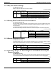
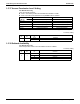
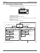
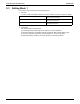

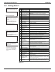
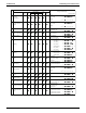
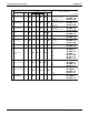
Table Of Contents

Field Settings from Outdoor Unit SiUS281811E
142 Part 5 Field Settings and Test Operation
2.4 Setting Mode 2
The numbers in the No. column represent the number of times to press the SET
(BS2) button.
noitpircseDmeti gnitteS.oN
1
Cool / heat unified
address
Sets address for cool / heat unified operation.
2
Low noise / demand
address
Address for low noise / demand operation
3 Test operation settings
Used to conduct test operation without making changes to the
PCB and replacing the refrigerant, after the completion of
maintenance.
5 Indoor unit forced fan H Allows forced operation of indoor fan while unit is stopped. (H tap)
6
Indoor unit forced
operation
Allows forced operation of indoor unit.
8 Te setting Target evaporation temperature for cooling
9 Tc setting Target condensation temperature for heating
10
Defrost changeover
setting
Changes the temperature condition for defrost and sets to quick
defrost or slow defrost.
12
External low noise /
demand setting
Reception of external low noise or demand signal
13 AIRNET address Set address for AIRNET.
16
Setting of heat pump
lockout 1
Make this setting for heat pump lockout.
19
Emergency automatic
heat pump lockout
Heat pump is automatically locked out in the event of a system
failure.
20
Additional refrigerant
charge operation
setting
Carries out additional refrigerant charge operation.
21
Refrigerant
recovery / vacuuming
mode setting
Sets to refrigerant recovery or vacuuming mode.
22
Night-time low noise
setting
Sets automatic nighttime low noise operation in a simple way.
The operating time is based on Starting Set and Ending Set.
25
Setting of low noise
level
Sets low noise level when the low noise signal is received.
26
Night-time low noise
operation start setting
Sets starting time of nighttime low noise operation.
(Night-time low noise setting is also required.)
27
Night-time low noise
operation end setting
Sets ending time of nighttime low noise operation.
(Night-time low noise setting is also required.)
28
Power transistor check
mode
∗Check after
disconnection of
compressor wires
Used for trouble diagnosis of DC compressor. Since the waveform
of inverter is output without wiring to the compressor, it is
convenient to probe whether the trouble comes from the
compressor or PCB.
29
Capacity precedence
setting
If the capacity control is required, the low noise control is
automatically released by this setting during carrying out low noise
operation and night-time low noise operation.
30 Demand setting 1
Changes target value of power consumption when demand control
1 is received.
32
Constant demand
setting
Enables demand control 1 without external input. (Effective to
prevent a problem that circuit breaker of small capacity is shut
down due to large load.)
37
Setting of heat pump
lockout 2
Make this setting for heat pump lockout.
41 Cooling comfort setting Selects comfort level of VRT cooling.
42 Heating comfort setting Selects comfort level of VRT heating.
47
Heat pump lockout
release differential
Heat pump would be resumed when the outdoor air temperature is
recovered by differential above the heat pump lockout
temperature.
50
Auxiliary heater
maximum allowable
temperature
Auxiliary heater is allowed to energize when the outdoor air
temperature is smaller than the auxiliary heater maximum
allowable temperature.
56
Auxiliary heater
maximum allowable
temperature release
differential
Auxiliary heater is not allowed to energize when the outdoor air
temperature is recovered by differential above the auxiliary heater
maximum allowable temperature.
57
Heat pump lockout
temperature
Heat pump would be locked out when the outdoor air temperature
is smaller than the heat pump lockout temperature. This setting is
only effective when heat pump lockout mode has been set.
Selection of setting items
Selection of setting conditions
Press the MODE (BS1) button for 5
seconds and enter the setting mode
2.
Press the SET (BS2) button and
select a setting item according to the
LED pattern shown in the table on
the right.
↓
Press the RETURN (BS3) button
and decide the item. (The present
setting condition is shown.)
Press the RETURN (BS3) button
and return to the initial status of
setting mode 2.
∗ If you become unsure of how to
proceed, press the MODE (BS1)
button and return to the setting
mode 1.
Press the SET (BS2) button and
select to the setting condition you
want.
↓
Press the RETURN (BS3) button and
decide the condition.