
Service Manual
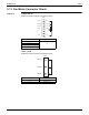
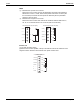
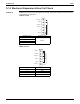
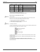
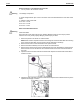
Table Of Contents

Check SiUS281811E
282 Part 6 Service Diagnosis
Warning
Warning
Electrical Checks - Low Voltage Control Circuits
1. Turn on power to air handler or modular.
Line Voltage now present.
2. Check voltage between pins on the 4-wire motor control harness between the motor and control
board.
3. Voltage on pins should read:
Pins 1 to 4 = 3.3vdc
Pins 1 to 2 = 3.3vdc
Pins 3 to 4 = 15vdc
Motor Control/End Bell Checks
HIGH VOLTAGE!
Disconnect ALL power before servicing or installing. Multiple power sources may be present.
Failure to do so may cause property damage, personal injury or death.
1. Disconnect power to air handler or modular blower.
NOTE: Motor contains capacitors that can hold a charge for several minutes after disconnecting
power. Wait 5 minutes after removing power to allow capacitors to discharge.
2. Disconnect the motor control harness and motor power harness.
3. Remove the blower assembly from the air handler or modular blower.
4. Remove the (3) screws securing the control/end bell to the motor. Separate the control/end bell.
Disconnect the 3-circuit harness from the control/end bell to remove the control/end bell from
the motor.
5. Inspect the NTC thermistor inside the control/end bell. Replace control/end bell if thermistor is
cracked or broken.
6. Inspect the large capacitors inside the control/end bell. Replace the control/end bell if any of the
capacitors are bulging or swollen.