
Service Manual
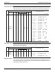
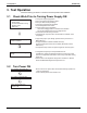
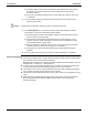
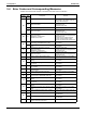
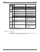
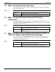
Table Of Contents

SiUS281811E Test Operation
Part 5 Field Settings and Test Operation 157
Warning
Caution
Caution
Caution
3.3 Test Operation
To start smoothly, a crankcase heater is equipped to the unit. To power up the crankcase heater in
advance, be sure to turn on the power supply 6 hours before operation.
Be sure to inform other installers or attach the front panel well before leaving with the power supply
turned on for the outdoor unit.
Before powering on
Protect the electronic components with insulating tape in accordance with the "Service
Precautions" label attached to the front panel.
All indoor units connected with the outdoor unit will operate automatically after powering on. To
ensure safety, ensure that the indoor unit installation has been completed.
1. Powering on ~ test operation
Make sure to perform a test run first after installation (If the unit is operated with the indoor unit
remote controller but without performing a test operation, the error code U3 will be indicated on
the display of the remote controller and the unit will not operate normally).
After turning on the power supply, do not touch any switches excluding button switches and
changeover switches when setting the outdoor unit PCB (A2P).
(For positions of the button switches (BS1~5) and changeover switches (DS1-1, 2) on the PCB,
refer to the "Service Precautions" label)
Check the state of the outdoor units and fault wiring with this operation.
To power up the crankcase heater in advance, be sure to turn on the power supply 6 hours before
operation.
Don't touch the switches other than button switches and changeover switches of the PCB (A2P)
during setting. Doing so may result in electric shock.
Power supply has been turned on for outdoor unit, be careful to avoid electric shock.
(1)
Attach the front panel of the outdoor unit.
Turn on the power supply of the outdoor and indoor units.
(2)
Remove the front panel of the outdoor unit.
Check LED display of the outdoor unit PCB (A1P, A2P), to observe whether data
transmission is normal.
Outdoor
unit PCB
A1P A2P
LED
display
(Factory
setting)
SERVICE
MONITORING
LAMP
MODE
READY /
ABNORMAL
C/H CHANGEOVER
LOW NOISE DEMAND
IND MASTER SUB
HAP H1P H2P H3P H4P H5P H6P H7P
lhhkh h h h
LED display h Light OFF k Light ON l Blinking
(3)
If customer wishes to perform LOW NOISE operation or DEMAND operation, perform
setting with the push buttons (BS1 ~ 5) on outdoor unit PCB (A2P).
Operate the push buttons from the opening of the insulating cover. (See Protective
range of the "Service Precautions" label for details)
Set the push buttons (BS1 ~ 5) after making sure the service monitoring lamp has
been ON.