
Service Manual
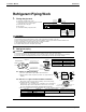
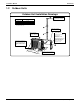
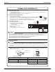
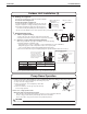
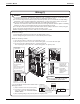
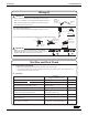
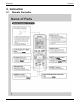
Table Of Contents

Installation Manual SiUS04-921
64 System Configuration
1.2 Outdoor Units
Outdoor Unit Installation Drawings
Wrap the insulation pipe with
the finishing tape from bottom
to top.
In sites with poor drainage, use
block bases for outdoor unit.
Adjust foot height until the unit
is leveled. Otherwise, water
leakage or pooling of water may
occur.
22-5/8 (574)
(Foot bolt-hole centers)
(F
rom unit’s side)
Where there is a danger of the unit
falling, use foot bolts, or wires.
(Foot bolt-hole
centers)
12-1/4 (311)
Unit: inch (mm)
How to remove the stop valve cover.
Remove the screw on the
stop valve cover.
Slide the lid downward
to remove it.
How to attach the stop valve cover.
Insert the upper part of the
stop valve cover into the
outdoor unit to install.
Tighten the screws.
Stop valve cover
O.D. 3/8 inch (9.5mm)
Gas pipe
Liquid pipe
O.D. 1/4 inch (6.4mm)
26ft (8m)
32ft (10m)Max. allowable length
Max. allowable height
*
No refrigerant needs to be added if the piping does not
exceed the maximum length.
4-1/8 (105.5)
Allow space for piping
and electrical servicing.
9-7/8” (250mm) from w
all
Allow 11-13/16 inch
(300mm) of work space
below the ceiling surface.