
Service Manual
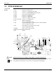

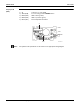
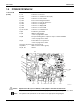
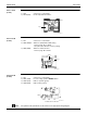
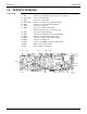
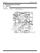
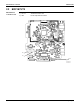
Table Of Contents

Indoor Unit SiUS121502E
22 Printed Circuit Board Connector Wiring Diagram
1.3 FDXS09/12LVJU, CDXS15/18/24LVJU
Control PCB
(A1P)
Caution Replace the PCB if you accidentally cut the jumpers other than JA, JB, and JC.
Jumpers are necessary for electronic circuit. Improper operation may occur if you cut any of them.
Note: The symbols in the parenthesis are the names on the appropriate wiring diagram.
1) S1 Connector for AC fan motor
2) S7 Connector for AC fan motor (Hall IC)
3) S21 Connector for centralized control (HA)
4) S26 Connector for display PCB
5) S32 Connector for indoor heat exchanger thermistor
6) H1, H2, H3 Connector for terminal board
7) FG (GND) Connector for terminal board (ground)
8) JA Address setting jumper
∗ Refer to page 189 for detail.
9) JB Fan speed setting when compressor stops for thermostat OFF
∗ Refer to page 191 for detail.
10) JC Power failure recovery function (auto-restart)
∗ Refer to page 191 for detail.
11) LED A LED for service monitor (green)
12) FU1 (F1U) Fuse (3.15 A, 250 V)
13) V1 (V1TR) Varistor
H2
H1
H3
FG
JB
S21
2P292535-1
LED A JCJA
S7
S1
FU1
S26
V1
S32