
Service Manual
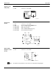
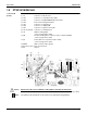

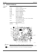
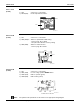
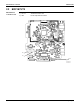
Table Of Contents

SiUS121502E Indoor Unit
Printed Circuit Board Connector Wiring Diagram 23
Display PCB
(A2P)
LED 1 does not function.
Note: The symbols in the parenthesis are the names on the appropriate wiring diagram.
1) S1 Connector for control PCB
2) SW1 (S1W) Forced cooling operation ON/OFF button
3) LED2 (H2P) LED for timer (yellow)
4) LED3 (H3P) LED for operation (green)
5) RTH1 (R1T) Room temperature thermistor
S1
LED3
LED2
SW1
2P084375-1
RTH1
1