
MXS Service Manual
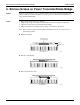
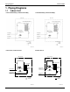
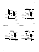
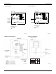
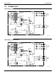
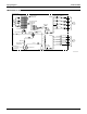

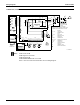
Table Of Contents

SiUS121736EA Wiring Diagrams
Appendix 256
2. Wiring Diagrams
2.1 Indoor Unit
CTXG09/12/18QVJUW(S), FTXR09/12/18TVJUW(S)
Note: A1P: Control PCB
A2P: Display/signal receiver PCB
A3P: INTELLIGENT EYE sensor PCB
Refer to Part 3 for Printed Circuit Board Connector Wiring Diagram.
3D103375
BLK
BLK
BLK
BLK
BLK
BLK
BLK
BLK
BLK
BLK
BLK
BLK
BLK
BLK
BLK
BLK
BLK
BLK
BLK
BLK
RED
ORG
YLW
PNK
BLU
RED
ORG
YLW
PNK
BLU
RED
ORG
YLW
BLU
PNK
BLK
BLK
BLK
BLK
BLK
BLK
BLK
BLK
BLK
BLK
BLK
BLK
BLK
BLK
BLK
BLK
BLK
BLK
BLK
BLK
BLK
WHT
RED
BLU
BRN
ORG
WHT
RED
GRN/YLW
GRN/YLW
RED
ORG
YLW
BLU
OUTDOOR
INDOOR
Field wiring
NOTE When the main power is turned off and then back on again, operation will resume automatically.
Wiring diagram
FG
F1U, F2U
H1P, H2P
R1T, R2T
S25-S200
S1W
S1C
X1M
BZ
M1F
M1S-M3S
M1
A1P-A3P
TRC
WRC
IES
SR
H1-H3
MR10
V1
C101, C102
: Frame ground
: Fuse
: Pilot lamp
: Thermistor
: Connector
: Operation switch
: Limit switch
: Terminal strip
: Buzzer
: Fan motor
: Swing motor
: Stepper motor
: Printed circuit board
: Transmission circuit
: Wireless remote control
: Intelligent Eye sensor
: Rectifier
: Signal receiver
: Ground
: Harness
: Magnetic relay
: Varistor
: Capacitor