
MXS Service Manual
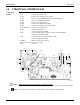
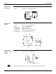
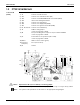
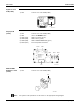
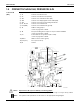
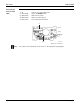
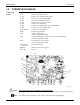
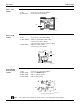
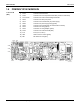
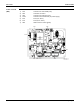
Table Of Contents

Indoor Unit SiUS121736EA
29 Printed Circuit Board Connector Wiring Diagram
Signal Receiver
PCB (PCB2)
Display PCB
(PCB3)
INTELLIGENT
EYE Sensor PCB
(PCB4)
Note: The symbols in the parenthesis are the names on the appropriate wiring diagram.
1) S48 Connector for control PCB (PCB1)
3P210728-1
S48
1) S49 Connector for control PCB (PCB1)
2) SW1 Indoor unit ON/OFF button
3) LED1 (H1P) LED for operation (green)
4) LED2 (H2P) LED for timer (yellow)
5) LED3 (H3P) LED for INTELLIGENT EYE (green)
6) RTH1 (R1T) Room temperature thermistor
3P210728-1
RTH1
SW1
S49
LED3 LED2 LED1
1) S26 Connector for control PCB (PCB1)
3EB86013-1
S26