English INSTALLATION MANUAL Français DAIKIN ROOM AIR CONDITIONER Installation manual Manuel d’installation Manual de instalación MODELS CTXG09QVJUW CTXG12QVJUW CTXG18QVJUW CTXG09QVJUS CTXG12QVJUS CTXG18QVJUS FTXR09TVJUW FTXR12TVJUW FTXR18TVJUW FTXR09TVJUS FTXR12TVJUS FTXR18TVJUS Español R410A Split Series
Contents Safety Considerations ..................................... 1 Refrigerant Piping Work .................................. 9 Accessories ...................................................... 3 1. Flaring the pipe end ..................................................... 9 2. Refrigerant piping....................................................... 10 Choosing an Installation Site .......................... 3 Installation Tips .............................................. 11 1. Indoor unit ...
• Make sure that a separate power supply circuit is provided for this unit and that all electrical work is carried out by qualified personnel according to local, state, and national regulations. An insufficient power supply capacity or improper electrical construction may lead to electric shock or fire. • Make sure that all wiring is secured, that specified wires are used, and that no external forces act on the terminal connections or wires. Improper connections or installation may result in fire.
Accessories A Mounting plate B Mounting plate fixing screw M4 × 1” (M4 × 25mm) 1 D Wireless remote controller 5 E Remote controller holder 1 G Dry battery AAA.
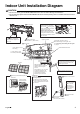
Indoor Unit Installation Diagram CAUTION • Do not hit or violently push the INTELLIGENT EYE sensor. This can lead to damage and malfunction. • Do not place large objects near the INTELLIGENT EYE sensor. Also keep heating units or humidifiers outside the sensor’s detection area. A Mounting plate How to attach the indoor unit Hook the hooks of the bottom frame to the A mounting plate. If the hooks are difficult to hook, remove the front grille.
Indoor Unit Installation 1. Installing the mounting plate The mounting plate should be installed on a wall which can support the weight of the indoor unit. 1)Temporarily secure the mounting plate to the wall, make sure that the plate is completely level, and mark the drilling points on the wall. 2)Secure the mounting plate to the wall with screws.
3) Pass the drain hose and refrigerant pipes through the wall hole, then position the indoor unit on the A mounting plate hooks, using the markings at the top of the indoor unit as a guide. A Mounting plate 3-2. Left-back piping 1) Replace the drain plug and drain hose. How to replace the drain plug and drain hose Replacing onto the left side 1) Remove the fixing screw on the right side and remove the drain hose. 2) Remove the drain plug on the left side and attach it to the right side.
Indoor Unit Installation 3-3. Wall embedded piping Follow the instructions given under left-back piping. 1) Insert the drain hose to this depth so it won’t be pulled out of the drain pipe. Insert the drain hose to this depth so it won’t be pulled out of the drain pipe. Inner wall 1-15/16” (50mm) or more Drain hose Vinyl chloride drain pipe (VP-30) Outer wall φ1-3/16” (30mm) or more 3-4. Bottom or left side piping 1) Cut off the pipe port cover with a copping saw.
4. Wiring Refer to the installation manual for the outdoor unit also. WARNING • Do not use tapped wires, extension cords, or starburst connections, as they may cause overheating, electric shock, or fire. • Do not use locally purchased electrical parts inside the product. (Do not branch the power for the drain pump, etc., from the terminal block.) Doing so may cause electric shock or fire. • Do not connect the power wire to the indoor unit. Doing so may cause electric shock or fire.
Indoor Unit Installation 5. Drain piping The drain hose should be inclined downward. 1) Connect the drain hose, as described on the right. No trap is permitted. Do not put the end of the hose in water. 2) Remove the upper front panel and the air filters. (Refer to removal method on page 11.) Pour some water into the drain pan to check the water flows smoothly. 3) If drain hose extension or embedded drain piping is required, use appropriate parts that match the hose front end.
2. Refrigerant piping CAUTION • Use the flare nut fixed to the main unit. (This is to prevent the flare nut from cracking as a result of deterioration over time.) • To prevent gas leakage, apply refrigeration oil only to the inner surface of the flare. (Use refrigeration oil for R410A.) • Use a torque wrench when tightening the flare nuts to prevent damage to the flare nuts and gas leakage.
Installation Tips 1. Removing and installing the upper front panel • Removal method 1) Open the upper front panel. 2) Slide the front panel locks on the back of the front panel upward to release the locks (left and right sides). 3) Remove the panel shafts on both sides from the shaft holes, and dismount the upper front panel.
7) Wear protection gloves and insert both hands under the front grille as shown in the figure. 8) Remove the front grille from the 3 upper hooks by pushing up the top side of the front grille, pull the front grille toward you by holding both ends of the front grille, and dismount the front grille.
Installation Tips 5. When connecting to an HA system (wired remote controller, central remote controller etc.) • Removal methods for metal plate electrical wiring box covers 1) Remove the upper front panel and front grille. (Refer to the removal method on page 11.) 2) Remove the electrical wiring box. (1 screw) 3) Remove the 4 tabs and dismount the metal plate electrical wiring box cover (A). 4) Pull down the hook on the metal plate electrical wiring box cover (B), and remove a single tab.
Trial Operation and Testing 1. Trial operation and testing • Trial operation should be carried out in either COOL or HEAT operation. 1-1. Measure the supply voltage and make sure that it is within the specified range. 1-2. In COOL operation, select the lowest programmable temperature; in HEAT operation, select the highest programmable temperature. 1-3.
The two-dimensional bar code is a manufacturing code.