
MXS Service Manual
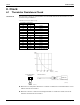
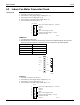
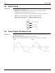
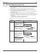
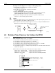

Table Of Contents

Check SiUS121736EA
209 Service Diagnosis
8. Check
8.1 Thermistor Resistance Check
Check No.01 Disconnect the connectors of the thermistors from the PCB, and measure the resistance of each
thermistor using a multimeter.
The data is for reference purpose only.
When the room temperature thermistor is soldered on a PCB, remove the PCB from the control
PCB to measure the resistance.
When the connector of indoor heat exchanger thermistor is soldered on a PCB, remove the
thermistor and measure the resistance.
Thermistor temperature
Resistance (kΩ)
°C °F
–20 –4 197.8
–15 5 148.2
–10 14 112.1
–5 23 85.60
0 32 65.93
5 41 51.14
10 50 39.99
15 59 31.52
20 68 25.02
25 77 20.00
30 86 16.10
35 95 13.04
40 104 10.62
45 113 8.707
50 122 7.176
(R25°C (77°F) = 20 kΩ, B = 3950 K)
(kΩ)
150
100
50
–15 0 15 30 45
(R14467)
5 32 59 86 113
(˚C)
(˚F)
Multimeter
(R20505)
Room temperature
thermistor
Multimeter
Resistance range
Other thermistors
(R23371)