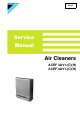
Si-64 Service Manual Air Cleaners ACEF 3AV1-(C)(H) ACEF 4AV1-(C)(H)
Si-64 $LU#&OHDQHUV ACEF 3AV1-(C)(H) ACEF 4AV1-(C)(H) 1. Safety Cautions...................................................................................... iii 1.1 Cautions and Warnings ........................................................................... iii 1.2 Using Icons...............................................................................................v 1.3 Using Icons List ........................................................................................
Si-64 Part 5 Removal Procedure ........................................................31 1. In Case of ACEF4AV1-(C)(H) ...............................................................33 1.1 1.2 1.3 1.4 1.5 1.6 1.7 Removal of External Accessories ..........................................................33 Removal of Ionizing Wire .......................................................................36 Removal of Electrical Parts (Inverter Lamp)...........................................37 Removal of PCB.
Si-64 Safety Cautions 1. Safety Cautions 1.1 Cautions and Warnings Read the following warnings and cautions BEFORE operating the system and use it correctly. „ This manual classifies the precautions to the user into the following two categories. Each mention important cautions on safety, so be sure to keep them. WARNING CAUTION Failure to follow a warning is very likely to result in such grave consequences as death or serious injury.
Safety Cautions Si-64 Caution Do not use the equipment in a place filled with oily smoke such as a kitchen or in a place filled with combustible gas, corrosive gas or metal dust. Otherwise fire and equipment malfunction can result. Do not use in humid places or places which might be wet, such as bathrooms. Contact with water can lead to electric shock or damage the equipment. Select a sturdy wall or pillar when mounting the equipment on a wall.
Si-64 Safety Cautions Caution Do not block the intake or outlet. Blocked openings can reduce capacity (air will not be cleaned throughout the entire room) and/or damage the equipment. Do not place water containers such as fish bowls and flower vases near the equipment. Water can cause electrical shock and equipment malfunction when it enters the equipment. Do not wipe with benzene or thinner, or spray with insecticide. Such substances can cause cracking, electric shock and/or fire.
Safety Cautions vi Si-64
Si-64 3DUW#4 ,QIRUPDWLRQ 1. General Description ................................................................................3 1.1 Introduction of Functions ..........................................................................3 1.2 Accessories ..............................................................................................4 1.3 Tips for Appropriate Use ..........................................................................5 2. Names and Functions of the Operating Section .........
Si-64 2 Information
Si-64 General Description 1. General Description 1.1 Introduction of Functions Dust Collection Removes minute dust particles from room air. Deodorizing Effectively removes cigarette odors, raw garbage odors and body odors. Harmful Gas Removal Breaks down automobile emissions (NOx) and new home odors. Antiviral/ Disinfecting Effect Removes and inactivates captured germs and viruses. Convenient Ion Filter Roll Easy, economical and inexpensive filter replacement.
General Description 1.2 Accessories Contents of Accessories 4 Si-64 Check the following accessories have been included in the product package.
Si-64 1.3 General Description Tips for Appropriate Use To remove house dust, set the unit near to the floor. To remove cigarette smoke, install the unit high on a wall. Installing the air cleaner as shown below improves air circulation in the room. While heating or coollng the room, air can be cleaned and temperature fluctuation minimized. Set Operating Mode as Needed. Auto Fan speed is controlled automatically depending on air quality. This mode ensures the most efficient operation.
Names and Functions of the Operating Section Si-64 2. Names and Functions of the Operating Section 2.1 Names and Functions of Parts Illustration A Front panel B Ion filter (roll) case Positively (+) charges minute dust particles not trapped by the prefilter. C Ion filter roll Working on the principle of electrostatic attraction, the negatively (-) charged filter catches and removes the positively (+) charged dust. D Air intake E Inverter lamp Activates the photocatalyst by illuminating it with light.
Si-64 Names and Functions of The Indicator Lamps 3. Names and Functions of The Indicator Lamps 3.1 Indicator Lamps and their Functions Illustration A “Ionizer needs cleaning” lamp Flashes when the ionizer is dirty. See page 14. B Timer settings The selected OFF timer setting is lit. As time elapses, the remaining time is displayed on the remote control. See page 14. C Pollen/Cigarette smoke mode lamps The corresponding lamp is lit when the unit is in either the pollen or cigarette smoke mode.
Names and Functions of The Indicator Lamps 8 Si-64 Information
Si-64 3DUW#5 )LHOG#6HWWLQJ 1. Setup and Installation............................................................................11 1.1 Setup ......................................................................................................11 1.2 Installation ..............................................................................................13 2. Operation of The Unit............................................................................14 2.1 How to Operate The Unit....................
Si-64 10 Field Setting
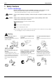
Si-64 Setup and Installation 1. Setup and Installation 1.1 Setup 1.1.1 How to Fit The Ion Filter CAUTION Always fit the prefilter and ion filter roll before use. Use without filters can damage the equipment. Remove the Front Panel. Hold the front panel by the left and right side handles, and pull forwards and out. Remove The Ion Filter (Roll) Case. Hold the ion filter (roll) case by the left and right side handles, and lift upward and out.
Setup and Installation Fit The Filter Roll. Si-64 1. Face the ion filter (roll) case downwards as shown below and fit the filter roll in the cutouts for the filter spool. 2. Unroll enough of the filter to cover the case and tuck the edges underneath the side tabs (×2). Then, fit the slits on leading edge over the pags on both sides of the case.
Si-64 1.2 Setup and Installation Installation Selecting an Installation Site. The unit can be either mounted on a wall or place on a flat surface such as a desk. Select a wall, shelf or floor that is sturdy enough to support the unit. ACEF3AV1: The unit weighs 6.7 kg. ACEF4AV1: The unit weighs 7.1 kg. Select a location that blows air across the entire room. For installation tips, see “Tips for appropriate use” page 5. How to Mount on Walls 1.
Operation of The Unit Si-64 2. Operation of The Unit 2.1 How to Operate The Unit Before attempting to use the unit, plug the power cable into a single phase 220-240V socket. The buttons and their functions are explained below.
Si-64 Explanation Operation of The Unit A To turn the lamps ON/OFF Pressing turns the inverter lamp ON and OFF. Turn the lamp OFF if light from the front panel is disturbing, for example at night. If left OFF, deodorizing and antiviral performance is reduced. B To set fan speed manually Every time is pressed, fan speed changes as follows. The fan starts at the last set fan speed. When “Quiet” is selected, the fan turns slowly enough not to disturb people in their sleep.
Operation of The Unit 16 Si-64 Field Setting
Si-64 3DUW#6 0DLQWHQDQFH 1. Cleaning of Prefilter and Ionizer............................................................19 1.1 Prefilter ...................................................................................................19 1.2 Ionizer.....................................................................................................20 2. Changing the Ion Filter (Roll) ................................................................21 2.1 How to Change the Ion Filter (Roll) ..............
Si-64 18 Maintenance
Si-64 Cleaning of Prefilter and Ionizer 1. Cleaning of Prefilter and Ionizer 1.1 Prefilter 1.1.1 How to Clean the Prefilter When to clean Once every 2 weeks or so. Procedure 1. Stop the unit and remove the power cable from its socket. 2. Remove the front panel. Hold the front panel by the left and right side handles, and pull forwards and out. 3. Remove the prefilter. Lie the front panel face down and unhook the prefilter from the panel (×4 hooks). 4. Clean the prefilter.
Cleaning of Prefilter and Ionizer 1.2 Ionizer 1.2.1 How to Clean the Ionizer If Procedure Si-64 (see page 7) on the front panel begins to flash, clean the ionizer. 1. Stop the unit and remove the power cabel from its socket. 2. Remove the front panel. See page 11. 3. Remove the ion filter (roll) case. Hold the ion filter (roll) case by the left and right side handles, and lift upwards and out. 4. Clean the ionizer.
Si-64 Changing the Ion Filter (Roll) 2. Changing the Ion Filter (Roll) 2.1 How to Change the Ion Filter (Roll) Explanation If (see page 6 on the front panel lightsup, change the ion filter. When the ion filter needs to be changed will depend on the conditions of use. If the unit is used where air is dirty, the ion filter will need changing more frequently. When using for 7 hours per day in auto mode, change the filter every 8 months. Procedure 1.
Changing the Ion Filter (Roll) Si-64 5. Attach the ion filter (roll) case to the unit. See step 3. 6. Replace the front panel on the unit. See page 11. 7. Plug the power cable into its socket. 8. Press the Reset button on the front panel. Use a ball-point pen or other pointed object. Check the Change Ion Filter lamp goes out A short acoustic buzzer can be heard when the sensor is reset.
Si-64 3DUW#7 7URXEOHVKRRWLQJ 1. Troubleshooting ....................................................................................25 1.1 1.2 1.3 1.4 Troubleshooting Equipment does not Operate. ................................................................25 Indicator does not Change from "Dirty" to "Clean." ................................27 Remote Controller Fails to Operate Equipment. ....................................28 Photocatalytic Operation does not Activate..................................
Si-64 24 Troubleshooting
Si-64 Troubleshooting 1. Troubleshooting 1.1 Equipment does not Operate. Method of Malfunction Detection Malfunction Decision Conditions Equipment cannot be operated by remote controller or switch on main unit. Supposed Causes „ „ „ „ Faulty door switch (safety switch assembly) Blown fuse Faulty transformer Faulty printed circuit board (control PCB assembly, display PCB assembly) Troubleshooting Check door switch (safety switch assembly).
Troubleshooting Si-64 Troubleshooting From previous page Check 12-volt power supply (between X12A (1) and (4)). Is voltage higher than 11.5 VDC and lower than 12.5 VDC? NO Replace control PCB (control PCB assembly). YES Check 5-volt power supply (between X9A (1) and (4)). Is voltage NO higher than 4.5 VDC and lower than 5.5 VDC? Replace control PCB (control PCB assembly). YES Check connector connection of A2P display PCB assembly. Is connection normal? NO Correct connector connection.
Si-64 1.2 Troubleshooting Indicator does not Change from "Dirty" to "Clean." Method of Malfunction Detection Malfunction Decision Conditions Air contamination indicator does not change to "clean" even when equipment is operated in ventilated room for a whole day. Supposed Causes „ Faulty harness „ Faulty sensor Troubleshooting Check connector connection. Are X14A and X101A normal? NO Correct connector connection YES Check humidity at installation site.
Troubleshooting 1.3 Si-64 Remote Controller Fails to Operate Equipment. Method of Malfunction Detection Malfunction Decision Conditions Switches on main unit work properly, but remote controller fails to operate equipment. Supposed Causes „ Noise generated by fluorescent lamps „ Faulty remote controller „ Faulty PCB Troubleshooting Check batteries in remote controller. Does problem remain after new batteries are installed? NO Battery consumption YES Check location conditions.
Si-64 1.4 Troubleshooting Photocatalytic Operation does not Activate. Method of Malfunction Detection Malfunction Decision Conditions Photocatalytic operation does not activate during equipment operation (lamp does not light). Supposed Causes „ Faulty lamp „ Faulty transformer „ Faulty PCB Troubleshooting Check connector and harness connection. Is connection normal? NO Correct connection YES Check power supply voltage (A1P-X1A).
Troubleshooting 30 Si-64 Troubleshooting
Si-64 3DUW#8 5HPRYDO#3URFHGXUH 1. In Case of ACEF4AV1-(C)(H) ...............................................................33 1.1 1.2 1.3 1.4 1.5 1.6 1.7 Removal Procedure Removal of External Accessories..........................................................33 Removal of Ionizing Wire .......................................................................36 Removal of Electrical Parts (Inverter Lamp)...........................................37 Removal of PCB..........................................
Si-64 32 Removal Procedure
Si-64 In Case of ACEF4AV1-(C)(H) 1. In Case of ACEF4AV1-(C)(H) 1.1 Removal of External Accessories Procedure Step Warning Be sure to turn off all power supplies before disassembling work Procedure 1 External appearance 2 Tilt main body to remove stand.
In Case of ACEF4AV1-(C)(H) Step Procedure 3 Remove front panel 4 Disengage hooks located at four of corners of the filter to remove prefilter located at rear side of panel.
Si-64 In Case of ACEF4AV1-(C)(H) Step 6 Procedure Points Main components Removal Procedure 35
In Case of ACEF4AV1-(C)(H) 1.2 Removal of Ionizing Wire Procedure Step Warning Be sure to turn off all power supplies before disassembling work Procedure 1 Push the hook using (-) screw driver to remove ionizing wire fixing plate. 2 Remove ionizing wire 3 Peel off sealing strips at top of main body.
Si-64 1.3 In Case of ACEF4AV1-(C)(H) Removal of Electrical Parts (Inverter Lamp) Procedure Step Warning Be sure to turn off all power supplies before disassembling work Procedure 1 Remove eight screws. Remove display box before remove a screw located at bottom right of main body front side. 2 Remove catalyst filter retainer. 3 Remove catalyst filter.
In Case of ACEF4AV1-(C)(H) Step Procedure 4 Turn main body over, then remove back panel. 5 Disconnect CN2 connector located at bottom left of main body rear side.
Si-64 In Case of ACEF4AV1-(C)(H) Step Procedure 6 Turn front side of main body up, then remove inverter lamps from lamp sockets. 7 Pull out connector for inverter lamp.
In Case of ACEF4AV1-(C)(H) 1.4 Removal of PCB Procedure Step Warning Be sure to turn off all power supplies before disassembling work Procedure 1 Dismount a screw located at bottom right of main body to remove display box. 2 Disengage 10 hooks. 3 Disengage the hooks to remove display PCB.
Si-64 In Case of ACEF4AV1-(C)(H) Step 4 Procedure Points Be careful not to lose protective sheet when removing gas sensor PCB.
In Case of ACEF4AV1-(C)(H) Step 5 42 Si-64 Procedure Points Location of PCBs is shown in the following illustrations.
Si-64 1.5 In Case of ACEF4AV1-(C)(H) Removal of Fan Motor Procedure Step 1 Warning Be sure to turn off all power supplies before disassembling work Procedure Points Remove back panel to remove fan securing nut. Caution When reassembling fan, match the Dcut direction of fan and shaft. 2 Disconnect connector. Caution When installing motor mounting plate, put the surface with protrusions up side.
In Case of ACEF4AV1-(C)(H) Step 3 44 Si-64 Procedure Points Remove three screws on motor mounting plate.
Si-64 1.6 In Case of ACEF4AV1-(C)(H) Removal of Safety Switch Procedure Step Warning Be sure to turn off all power supplies before disassembling work Procedure 1 Remove door switch cover 2 To remove safety switch, push it out from back side.
In Case of ACEF4AV1-(C)(H) 1.7 Installation of Power Cable Procedure Step Warning Be sure to turn off all power supplies before disassembling work Procedure 1 Insert cord bushing to the hole at front side of main body. 2 Adjust the bushing position in order to insert back panel into groove of cord bushing before install back panel. 3 Installation of power cable is complete.
Si-64 3DUW#9 5HIHUHQFH#'DWD 1. Optional Accessories ............................................................................49 1.1 Specifications .........................................................................................49 2. Wiring Diagram .....................................................................................50 2.1 ACEF3AV1-C, H.....................................................................................50 2.2 ACEF4AV1-C, H........................................
Si-64 48 Reference Data
Si-64 Optional Accessories 1. Optional Accessories 1.1 Specifications Unit Model ACEF3AV1-C,-H ACEF4AV1-C,-H Required Power Supply 220-240V 50Hz Outer Dimensions 395×462×180 (Without Stand) 395×479×184 (When Installed on Stand) Rated Power Consumption (W) 43 62 Air Blow Rate (m³/min) High Speed 3.0 Normal Speed 2.0 Quiet 0.6 Low Speed 1.4 High Speed 3.8 Normal Speed 2.7 Quiet 0.6 Low Speed 1.7 Applicable Room Area ~30m² ~40m² Weight 6.7 7.
Wiring Diagram Si-64 2. Wiring Diagram 2.
Si-64 2.
Parts List Si-64 3. Parts List 3.
Si-64 3.2 Parts List Parts List ACEF3/4AV1-C, H No. Index Parts No. Parts Name Drwg. No.
Parts List No. Index Si-64 Parts No. Parts Name Drwg. No.
Si-64 ,QGH[ $ 5 Accessories ..............................................................4 Air Blow Rate (m³/min) ...........................................49 Antiviral/Disinfecting Effect .......................................3 Applicable Room Area ...........................................49 Rated Power Consumption (W) ............................. 49 Remote Controller Fails to Operate Equipment. ... 28 Removal of Electrical Parts (Inverter Lamp) .......... 37 Removal of External Accessories .....
Si-64 ii Index
Si-64 'UDZLQJV#)#)ORZ#&KDUWV $ , Air Quality lamps ......................................................7 Before changing filters, cleaning the equipment or moving it, turn it OFF and unplug the power cable. ............................ iii If not using the unit for long periods of time, unplug the power cable. ....................................v Indicator does not Change from "Dirty" to "Clean." ................................... 27 Indicator Lamps and their Functions .......................
Si-64 : Wiring Diagram ......................................................50 ACEF3AV1-C, H ..............................................50 ACEF4AV1-C, H ..............................................
Head office: Umeda Center Bldg., 4-12, Nakazaki-Nishi 2-chome, Kita-ku, Osaka, 530-8323 Japan Zandvoordestraat 300, B-8400 Oostende, Belgium Tokyo office: Shinjuku Sumitomo Bldg., 6-1 Nishi-Shinjuku 2-chome, Shinjuku-ku, Tokyo, 163-0235 Japan z For further improvement, specifications or designs are subject to change without prior notice.