
Installation Instructions


1-3
English
INSTALLATION DIAGRAM (AHQ71/100/125CV1)
Preliminary Site Survey
Voltage supply fluctuation must not exceed ±10% of rated
voltage. Electricity supply lines must be independent
of welding transformer which can cause high supply
fluctuations.
Ensure that the location is convenient for wiring, piping
and drainage.
•
•
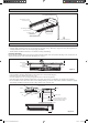
Standard Mounting
Ensure that the overhead supports are strong enough to hold
the weight of the unit. Position the hanger rods (wall mounting
bracket for floor standing), and check for its alignment with
the unit as shown in Figure A. Also, check that the hangers
are secured and the base of the fan coil unit is leveled in both
horizontal directions, taking into account the gradient for
drainage flow as recommended in Figure B.
Figure A
All dimensions are in mm
A
E
B
CD
F
G
H
INSTALLATION OF THE INDOOR UNIT (AHQ71/100/125CV1)
TO OUTDOOR UNIT
Air Discharge Louver
Signal Receiver
Indicator Light
Air Intake Grille
Wrap the Insulated pipe with the
finishing tape from bottom to top
Air Filters
(Inside Air Intake Grille)
Dimension
Model
ABCDEFGH
AHQ71CV1 1320 635 255 134 1222 49 148 120
AHQ100CV1 1538 635 255 134 1440 49 148 120
AHQ125CV1 1786 635 255 134 1688 49 148 120
1 IM 5CEY-0711(5)SIESTA-EN.indd 31 IM 5CEY-0711(5)SIESTA-EN.indd 3 10/12/17 9:46:45 AM10/12/17 9:46:45 AM