00_CV_3P207974-2D.
ARX20GV1B, ARX25GV1B, ARX35GV1B, ARX20JV1B, ARX25JV1B, ARX35JV1B DAIKIN INDUSTRIES, LTD. Shinri Sada Manager Quality Control Department 11th. of Sep. 2009 Low Voltage 2006/95/EC Electromagnetic Compatibility 2004/108/EC * Umeda Center Bldg., 2-4-12, Nakazaki-Nishi, Kita-ku, Osaka, 530-8323 Japan 74736-KRQ/EMC97-4957 KEMA Quality B.V. DAIKIN.TCF.015 M12/09-2009 3SB64526-9D.
01_EN_3P207974-2D.fm Page 1 Friday, September 4, 2009 1:45 PM Safety Precautions • Read these Safety Precautions carefully to ensure correct installation. • This manual classifies the precautions into WARNING and CAUTION. Be sure to follow all the precautions below: they are all important for ensuring safety. WARNING...............Failure to follow any of WARNING is likely to result in such grave consequences as death or serious injury. CAUTION...............
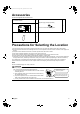
01_EN_3P207974-2D.fm Page 2 Friday, September 4, 2009 1:45 PM Accessories Accessories supplied with the outdoor unit: (A) Installation Manual 1 (B) Drain plug (Heat pump-Models) (C) Refrigerant charge label 1 1 There is on the bottom packing case. (D) Multilingual fluorinated greenhouse gases label 1 Precautions for Selecting the Location 1) Choose a place solid enough to bear the weight and vibration of the unit, where the operation noise will not be amplified.
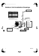
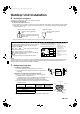
01_EN_3P207974-2D.fm Page 3 Friday, September 4, 2009 1:45 PM Outdoor Unit Installation Drawings Wrap the insulation pipe with the finishing tape from bottom to top. Max. allowable length 15m * Min. allowable length 1.5m Max. allowable height 12m Additional refrigerant required for refrigerant pipe exceeding 10m in length. 20g/m Gas pipe O.D. 9.5mm Liquid pipe O.D. 6.4mm * Be sure to add the proper amount of additional refrigerant. Failure to do so may result in reduced perfomance.
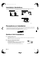
01_EN_3P207974-2D.fm Page 4 Friday, September 4, 2009 1:45 PM Installation Guidelines • Where a wall or other obstacle is in the path of outdoor unit’s intake or exhaust airflow, follow the installation guidelines below. • For any of the below installation patterns, the wall height on the exhaust side should be 1200mm or less.
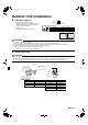
01_EN_3P207974-2D.fm Page 5 Friday, September 4, 2009 1:45 PM Outdoor Unit Installation 3. Flaring the pipe end. 1) Cut the pipe end with a pipe cutter. 2) Remove burrs with the cut surface facing downward so that the chips do not enter the pipe. 3) Put the flare nut on the pipe. 4) Flare the pipe. 5) Check that the flaring is properly made. (Cut exactly at right angles.) Remove burrs Flaring Set exactly at the position shown below.
01_EN_3P207974-2D.fm Page 6 Friday, September 4, 2009 1:45 PM 5. Purging air and checking gas leakage. • When piping work is completed, it is necessary to purge the air and check for gas leakage. WARNING 1) 2) 3) 4) Do not mix any substance other than the specified refrigerant (R410A) into the refrigeration cycle. When refrigerant gas leaks occur, ventilate the room as soon and as much as possible.
01_EN_3P207974-2D.fm Page 7 Friday, September 4, 2009 1:45 PM Outdoor Unit Installation 6. Refilling the refrigerant. Check the type of refrigerant to be used on the machine nameplate. Precautions when adding R410A Fill from the liquid pipe in liquid form. It is a mixed refrigerant, so adding it in gas form may cause the refrigerant composition to change, preventing normal operation. 1) Before filling, check whether the cylinder has a siphon attached or not.
01_EN_3P207974-2D.fm Page 8 Friday, September 4, 2009 1:45 PM Pump Down Operation In order to protect the environment, be sure to pump down when relocating or disposing of the unit. 1) 2) 3) 4) Remove the valve cap from liquid stop valve and gas stop valve. Carry out forced cooling operation. After five to ten minutes, close the liquid stop valve with a hexagonal wrench. After two to three minutes, close the gas stop valve and stop forced cooling operation.
01_EN_3P207974-2D.fm Page 9 Friday, September 4, 2009 1:45 PM Wiring WARNING 1) Do not use tapped wires, stranded wires, extension cords, or starburst connections, as they may cause overheating, electrical shock, or fire. 2) Do not use locally purchased electrical parts inside the product. (Do not branch the power for the drain pump, etc., from the terminal block.) Doing so may cause electric shock or fire. 3) Be sure to install an earth leakage breaker. (One that can handle higher harmonics.
01_EN_3P207974-2D.fm Page 10 Friday, September 4, 2009 1:45 PM CAUTION When connecting the connection wires to the terminal board using a single core wire, be sure to perform curling. Problems with the work may cause heat and fires. Strip wire end to this point. Good Excessive strip length may cause electrical shock or leakage. Wrong Stripping wire at terminal block 3) Pull the wire and make sure that it does not disconnect. Then fix the wire in place with a wire stop.
01_EN_3P207974-2D.fm Page 11 Friday, September 4, 2009 1:45 PM Test Run and Final Check 1. Trial operation and testing. 1-1 Measure the supply voltage and make sure that it falls in the specified range. 1-2 Trial operation should be carried out in either cooling or heating mode. ■ For heat pump • In cooling mode, select the lowest programmable temperature; in heating mode, select the highest programmable temperature. 1) Trial operation may be disabled in either mode depending on the room temperature.
00_CV_3P207974-2D.fm Page 2 Friday, September 4, 2009 1:41 PM Two-dimensional bar code is a code for manufacturing.