INSTALLATION MANUAL R410A Split Series Models RX20J3V1B RX25J3V1B RX35J3V1B RX20K2V1B RX25K2V1B RX35K2V1B
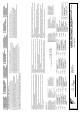
U Nove hospody 1/1155, 301 00 Plzen Skvrnany, Czech 5epublic Low Voltage 2006/95/EC Electromagnetic Compatibility 2004/108/EC * Takayuki Fujii Managing Director 1st of 1RY. 201 RX20J 9 %, RX25J V1B, RX35J V1B $5; - 9 % $5; - 9 % $5; - 9 % DAIKIN INDUSTRIES CZECH REPUBLIC s.r.
CE - DECLARACION-DE-CONFORMIDAD CE - DICHIARAZIONE-DI-CONFORMITA CE - ∆HΛΩΣΗ ΣΥΜΜΟΡΦΩΣΗΣ 10 09 08 07 19 ob upoštevanju določb: 20 vastavalt nõuetele: 21 следвайки клаузите на: 22 laikantis nuostatų, pateikiamų: 23 ievērojot prasības, kas noteiktas: 24 održiavajúc ustanovenia: 25 bunun koşullarına uygun olarak: 07 ** 08 ** 09 ** 10 ** 11 ** 12 ** 11 Information * enligt och godkänts av enligt Certifikatet .
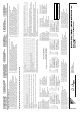
Safety Precautions • Read these Safety Precautions carefully to ensure correct installation. • This manual classifies the precautions into WARNING and CAUTION. Be sure to follow all the precautions below: they are all important for ensuring safety. WARNING......... Failure to follow any of WARNING is likely to result in such grave consequences as death or serious injury. CAUTION......... Failure to follow any of CAUTION may result in grave consequences in some cases.
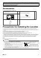
• Make sure to provide for adequate measures in order to prevent that the outdoor unit be used as a shelter by small animals. Small animals making contact with electrical parts can cause malfunctions, smoke or fire. Please instruct the customer to keep the area around the unit clean. • This appliance is intended to be used by expert or trained users in shops, in light industry and on farms, or for commercial and household use by lay persons. • Sound pressure level is less than 70 dB(A).
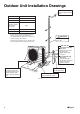
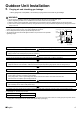
Outdoor Unit Installation Drawings Wrap the insulation pipe with the finishing tape from bottom to top. Max. allowable length 15m * Min. allowable length 1.5m Max. allowable height 12m Additional refrigerant required for refrigerant pipe exceeding 10m in length. 20g/m Gas pipe O.D. 9.5mm Liquid pipe O.D. 6.4mm * Be sure to add the proper amount of additional refrigerant. CAUTION Failure to do so may result in reduced perfomance. * The suggested shortest pipe length is 1.
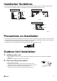
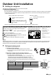
Installation Guidelines • Where a wall or other obstacle is in the path of outdoor unit’s intake or exhaust airflow, follow the installation guidelines below. • For any of the below installation patterns, the wall height on the exhaust side should be 1200mm or less.
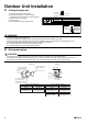
Outdoor Unit Installation 3. Flaring the pipe end. 1) Cut the pipe end with a pipe cutter. 2) Remove burrs with the cut surface facing downward so that the chips do not enter the pipe. 3) Put the flare nut on the pipe. 4) Flare the pipe. 5) Check that the flaring is properly made. (Cut exactly at right angles.) Remove burrs Flaring Set exactly at the position shown below. A Die Flare tool for R410A Conventional flare tool Clutch-type Clutch-type (Rigid-type) Wing-nut type (Imperial-type) A 0-0.
Outdoor Unit Installation 5. Purging air and checking gas leakage. • When piping work is completed, it is necessary to purge the air and check for gas leakage. WARNING 1) 2) 3) 4) Do not mix any substance other than the specified refrigerant (R410A) into the refrigeration cycle. When refrigerant gas leaks occur, ventilate the room as soon and as much as possible. R410A, as well as other refrigerants, should always be recovered and never be released directly into the environment.
Outdoor Unit Installation 6. Refilling the refrigerant. Check the type of refrigerant to be used on the machine nameplate. Precautions when adding R410A Fill from the liquid pipe in liquid form. It is a mixed refrigerant, so adding it in gas form may cause the refrigerant composition to change, preventing normal operation. 1) Before filling, check whether the cylinder has a siphon attached or not. (It should have something like “liquid filling siphon attached” displayed on it.
Pump Down Operation In order to protect the environment, be sure to pump down when relocating or disposing of the unit. 1) 2) 3) 4) Remove the valve cap from liquid stop valve and gas stop valve. Carry out forced cooling operation. After five to ten minutes, close the liquid stop valve with a hexagonal wrench. After two to three minutes, close the gas stop valve and stop forced cooling operation.
Wiring WARNING 1) Do not use tapped wires, stranded wires, extension cords, or starburst connections, as they may cause overheating, electrical shock, or fire. 2) Do not use locally purchased electrical parts inside the product. (Do not branch the power for the drain pump, etc., from the terminal block.) Doing so may cause electric shock or fire. 3) Be sure to install an earth leakage breaker. (One that can handle higher harmonics.
CAUTION When connecting the connecting wires to the terminal board using a single core wire, be sure to perform curling. Problems with the work may cause heat and fires. Strip wire end to this point. Excessive strip length may cause electrical shock or leakage. Good Wrong Stripping wire at terminal block 3) Pull the wire and make sure that it does not disconnect. Then fix the wire in place with a wire stop.
Test Run and Final Check 1. Trial operation and testing. 1-1 Measure the supply voltage and make sure that it falls in the specified range. 1-2 Trial operation should be carried out in either cooling or heating mode. For heat pump • In cooling mode, select the lowest programmable temperature; in heating mode, select the highest programmable temperature. 1) Trial operation may be disabled in either mode depending on the room temperature.
3P291651-9U 2014.