INSTALLATION MANUAL R410A Split Series Installation manual R410A Split series Models ATX20J2V1B ATX25J2V1B ATX35J2V1B English Installationsanleitung Split-Baureihe R410A Deutsch Manuel d’installation Série split R410A Français Montagehandleiding R410A Split-systeem Manual de instalación Serie Split R410A Manuale d’installazione Serie Multiambienti R410A !"#$%&ß'%( $")*+Ü,+*,-ò '%*%&(ýì$.
DAIKIN INDUSTRIES CZECH REPUBLIC s.r.o ATX20J2V1B, ATX25J2V1B, ATX35J2V1B Low Voltage 2006/95/EC Electromagnetic Compatibility 2004/108/EC * DAIKIN,TCF,015 N11/01-2011 DEKRA (NB0344) 74736-KRQ/EMC97-4957 3P290872-2 Takayuki Fujii Managing Director 1st of Jun.
Safety Precautions • Read these Safety Precautions carefully to ensure correct installation. • This manual classifies the precautions into WARNING and CAUTION. Be sure to follow all the precautions below: they are all important for ensuring safety. WARNING...............Failure to follow any of WARNING is likely to result in such grave consequences as death or serious injury. CAUTION...............Failure to follow any of CAUTION may result in grave consequences in some cases.
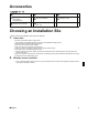
Accessories !"##$ %!&' A – L , A Mounting plate 1 E Remote controller holder 1 K Operation manual 1 B Titanium Apatite Photocatalytic Air-Purifying Filter 2 G AAA dry-cell batteries 2 L Installation manual 1 D Wireless remote controller 1 H Indoor unit fixing screws (M4 × 12L) 2 Choosing an Installation Site • Before choosing the installation site, obtain user approval. 1. Indoor unit.
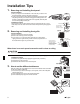
Installation Tips 1. Removing and installing front panel. • Removal method 1) Place your fingers in the indentations on the main unit (one each on the left and right sides), and open the panel until it stops. 2) Continue to open the front panel further while sliding the panel to the right and pulling it toward you in order to disengage the rotating shaft on the left side. To disengage the rotating shaft on the right side, slide the panel to the left while pulling it toward you.
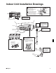
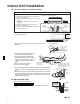
Indoor Unit Installation Drawings How to attach the indoor unit. Hook the claws of the bottom frame to the mounting plate. If the claws are difficult to hook, remove the front grille. How to remove the indoor unit. Push up the marked area (at the lower part of the front grille) to release the claws. If it is difficult to Front grille release, remove the front grille.
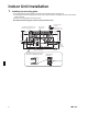
Indoor Unit Installation 1. Installing the mounting plate. • The mounting plate should be installed on a wall which can support the weight of the indoor unit. 1) Temporarily secure the mounting plate to the wall, make sure that the panel is completely level, and mark the boring points on the wall. 2) Secure the mounting plate to the wall with screws. Recommended mounting-plate retention spots and Dimensions Recommended mounting - plate retention spots (5 spots in all) 120.5 Use tape measure as shown.
2. Boring a wall hole and installing wall embedded pipe. • For walls containing metal frame or metal board, be sure to use a wall embedded pipe and wall cover in the feed-through hole to prevent possible heat, electrical shock, or fire. • Be sure to caulk the gaps around the pipes with caulking material to prevent water leakage. 1) Bore a feed-through hole of 65mm in the wall so it has a down slope toward the outside. 2) Insert a wall pipe into the hole. 3) Insert a wall cover into wall pipe.
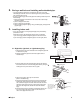
Indoor Unit Installation 3-2. Left-side, left-back, or left-bottom piping. How to replace the drain plug and drain hose. Drain hose attachment position • Replacing onto the left side 1) Remove the insulation fixing screws on the right to remove the drain hose. 2) Reattach the insulation fixing screw on the right as it was. * (Forgetting to attach this may cause water leakages.) 3) Remove the drain plug on the left side and attach it to the right side.
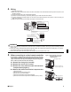
4. Wiring. 1) Strip wire ends (15mm). 2) Match wire colours with terminal numbers on indoor and outdoor unit’s terminal blocks and firmly screw wires to the corresponding terminals. 3) Connect the earth wires to the corresponding terminals. 4) Pull wires to make sure that they are securely latched up, then retain wires with wire retainer. 5) In case of connecting to an adapter system. Run the remote control cable and attach the S21. (Refer to 5. When connecting to a wired remote controller.
Indoor Unit Installation 5-5. Prepare the accessory (separate product) [Figure 2]. 1) Remove the cover from the accessory (separate product). 2) Insert the connection cord into connector “S21” (white) in the accessory (separate product). 3) Route each of the connection cords through the cut-outs in the accessory, then reinstall the accessory cover in its original position. 4) Insert the accessory (separate product) connector into connector “S403” in the indoor unit electrical component box.
6. !" #$%&' !()" )!(*+# ," &'-+&'"# #(.'.%$#/ Drain piping. 1) Connect the drain hose, as described right. 0( 1$%2 &) 2"$3&11"#/ 4( '(1 2*1 1!" "'# (5 1!" !()" &' .%1"$/ 2) Remove the air filters and pour some water into the drain pan to check the water flows smoothly. 3) If drain hose extension or embedded drain piping is required, use appropriate parts that match the hose front end.
Refrigerant Piping Work 2. Refrigerant piping. CAUTION 1) Use the flare nut fixed to the main unit. (To prevent cracking of the flare nut by aged deterioration.) 2) To prevent gas leakage, apply refrigeration oil only to the inner surface of the flare. (Use refrigeration oil for R410A.) 3) Use torque wrenches when tightening the flare nuts to prevent damage to the flare nuts and gas leakage. Align the centres of both flares and tighten the flare nuts 3 or 4 turns by hand.
Trial Operation and Testing 1. Trial operation and testing. 1-1 Measure the supply voltage and make sure that it falls in the specified range. 1-2 Trial operation should be carried out in either cooling or heating mode. • In cooling mode, select the lowest programmable temperature; in heating mode, select the highest programmable temperature. 1) Trial operation may be disabled in either mode depending on the room temperature. Use the remote controller for trial operation as described below.
MEMO 13 ■Portugues
MEMO ■Portugues 14
MEMO 15 ■Portugues
U Nove hospody 1/1155, 301 00 Plzen Skvrnany, Czech republic Zandvoordestraat 300, B-8400 Ostende, Belgium www.daikineurope.