
Service manual


SiBE05-722_C Check
Service Diagnosis 101
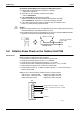
Diagnose method (Diagnose according to 6 LEDs lighting status.)
(1) If all the LEDs are lit uniformly, the compressor is defective.
→ Replace the compressor.
(2) If the LEDs are not lit uniformly, check the power module.
→ Refer to Check No.22.
(3) If NG in Check No.22, replace the power module.
(Replace the main PCB. The power module is united with the main PCB.)
If OK in Check No.22, check if there is any solder cracking on the PCB.
(4) If any solder cracking is found, replace the PCB or repair the soldered section.
If there is no solder cracking, replace the PCB.
Caution
(1) When the output frequency is low, the LEDs blink slowly. As the output frequency increases,
the LEDs blink quicker. (The LEDs look like they are lit.)
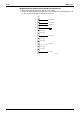
(2) On completion of the inverter analyzer diagnosis, be sure to re-crimp the FASTON terminals.
Otherwise, the terminals may be burned due to loosening.
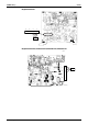
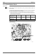
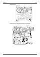
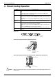
5.8 Rotation Pulse Check on the Outdoor Unit PCB
Check No.16 RK(X)S25/35E2V1B, RK(X)S25/35G2V1B
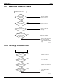
Make sure that the voltage of 320 ± 30 V is applied.
1. Set operation off and power off. Disconnect the connector S70.
2. Check that the voltage between the pins 4 - 7 is 320 VDC.
3. Check that the control voltage between the pins 3 - 4 is 15 VDC.
4. Check that the rotation command voltage between the pins 2 - 4 is 0 ~ 15 VDC.
5. Keep operation off and power off. Connect the connector S70.
6. Check whether 2 pulses (0 ~ 15 VDC) are output at the pins 1 - 4 when the fan motor is
rotated 1 turn by hand.
When the fuse is melted, check the outdoor fan motor for proper function.
If NG in step 2 → Defective PCB → Replace the outdoor unit PCB.
If NG in step 4 → Defective Hall IC → Replace the outdoor fan motor.
If OK in both steps 2 and 4 → Replace the outdoor unit PCB.
(R15292)
Direction of crimp
FASTON terminal
This size is shortened
by the crimp.
1
2
3
4
5
6
7
320 VDC
(R10811)
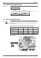
S70
PCB
Actual rotation pulse output (0 ~ 15 VDC)
Rotation command pulse input (0 ~ 15 VDC)
15 VDC