
Service manual


SiBE05-722_C Indoor Unit
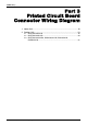
Printed Circuit Board Connector Wiring Diagram 17
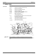
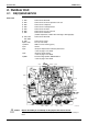
Power Supply
PCB
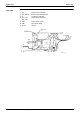
Display PCB
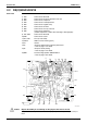
Signal Receiver
PCB
1) S36 Connector for control PCB
2) H1, H2, H3 Connector for terminal board
3) H4, H5, H6 Connector for AC fan motor
4) V1 Varistor
5) FU1 Fuse (3.15A, 250V)
S36
FU1
H2
H3
H4
H5
H6
H1
V1
2P084361-1
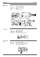
1) S25 Connector for control PCB
2) LED1 (H1P) LED for operation (green)
3) LED2 (H2P) LED for timer (yellow)
4) LED3 (H3P) LED for HOME LEAVE operation (red)
LED3 LED2 LED1
S25
2P084377-5
1) S27 Connector for control PCB
2) S31 (RTH) Connector for room temperature thermistor
3) SW1 (S1W) Forced cooling operation [ON/OFF] button
∗ Refer to page 110 for detail.
SW1
S31 (RTH)
PbF
SW1
I
RTH
WLU
3
C1
C2
C3
EX511 REV 12
S27
S27
2P084377-5
PHOTO
2P084377-