
Service manual

SiBE05-722_C Main Functions
Function and Control 27
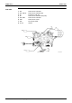
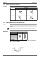
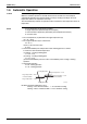
1.3 Airflow Direction Control
Auto-Swing The following table explains the auto swing process for cooling, dry, fan, and heating:
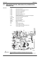
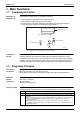
1.4 Fan Speed Control for Indoor Unit
Outline Phase control and fan speed control contains 9 steps: LLL, LL, SL, L, ML, M, MH, H, and HH.
The airflow rate can be automatically controlled depending on the difference between the room
thermistor temperature and the target temperature. This is done through phase control and Hall
IC control.
For more information about Hall IC, refer to the troubleshooting for fan motor on page 63.
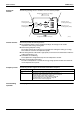
Automatic Fan
Speed Control
In automatic fan speed operation, the step “SL” is not available.
= The airflow rate is automatically controlled within this range when the [FAN] setting
button is set to automatic
.
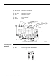
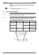
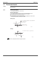
<Cooling>
The following drawing explains the principle of fan speed control for cooling.
Up and Down
Cooling / Dry / Fan Heating
Ceiling
Floor
40˚
20˚
(R2964)
(R2963)
95˚
65˚
(R2967)
40˚
20
˚
(R2966)
95˚
65
˚
Step Cooling Heating
LLL
LL
L
ML
M
MH
H
HH (POWERFUL)
(R6833)
(R6834)
Room thermistor temperature – target temperature
+1.5˚C
+0.5˚C
+2˚C
+1˚C
M
ML
L
Fan speed
(R12390)