INSTALLATION MANUAL SPLIT SYSTEM Air Conditioners MODELS (Ceiling mounted Multi flow cassette type) FCQG71EVEB FCQG100EVEB FCQG125EVEB FCQG140EVEB READ THESE INSTRUCTIONS CAREFULLY BEFORE INSTALLATION. KEEP THIS MANUAL IN A HANDY PLACE FOR FUTURE REFERENCE.
FCQG71EVEB FCQG100EVEB FCQG125EVEB FCQG140EVEB SPLIT SYSTEM Air Conditioners Installation manual CONTENTS 1. 2. 3. 4. 5. 6. 7. 8. 9. 10. 11. 12. 13. SAFETY PRECAUTIONS...............................................................................................1 BEFORE INSTALLATION ...............................................................................................3 SELECTING INSTALLATION SITE ................................................................................
• Make sure that a separate power supply circuit is provided for this unit and that all electrical work is carried out by qualified personnel according to local laws and regulations and this installation manual. An insufficient power supply capacity or improper electrical construction may lead to electric shocks or fire. • Make sure that all wiring is secured, the specified wires are used, and that there is no strain on the terminal connections or wires.
2. BEFORE INSTALLATION Do not exert pressure on the resin parts when opening the unit or when moving it after opening. Be sure to check the type of R410A refrigerant to be used before doing any work. (Using an incorrect refrigerant will prevent normal operation of the unit.) • When opening the unit or moving it after opening, be sure to lift it by holding on to the lifting lugs without exerting any pressure on other parts, especially, drain piping, and other resin parts. • Decide upon a line of transport.
2. OPTIONAL ACCESSORIES • The optional decoration panel and remote controller are required for this indoor unit. (Refer to Table 1, 2) • Check that the decoration panel is prepared. (For the installation of the decoration panel, refer to the installation manual attached to the decoration panel.
Points for explanation about operations The items with WARNING and CAUTION marks in the instruction manual are the items pertaining to possibilities for bodily injury and material damage in addition to the general usage of the product. Accordingly, it is necessary that you make a full explanation about the described contents and also ask your customers to read the instruction manual. 3.
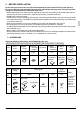
(3) Direction of the air discharge • Select the number of directions of the optimum air discharge for the shape or the position of the room. • Directions of the air discharge can be changed by installing a sealing material. • When installing a sealing material, the field setting from the remote controller is required. For details, refer the operation manual attached to the sealing materials. [Direction of air discharge] * All round * 4-way Fig.
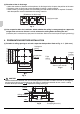
(2) Make the ceiling opening needed for installation where applicable. (For existing ceilings) • Refer to the paper pattern for installation (5) for ceiling opening dimensions. • Create the ceiling opening required for installation. From the side of the opening to the casing outlet, implement the refrigerant and drain piping and wiring for remote controller and indoor-outdoor unit casing outlet. Refer to ‘‘6. REFRIGERANT PIPING WORK’’, ‘‘7. DRAIN PIPING WORK’’ and ‘‘8. ELECTRIC WIRING WORK’’.
5. INDOOR UNIT INSTALLATION Installing optional accessories (except for the decoration panel) before installing the indoor unit is easier. However, for existing ceilings, install fresh air inlet component kit and branch duct before installing the unit. As for the parts to be used for installation work, be sure to use the provided accessories and specified parts designated by our company. (1) For new ceilings (1-1)Install the indoor unit temporarily. • Attach the hanger bracket to the suspension bolt.
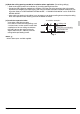
(1-3)Adjust the unit to the right position for installation. (Refer to “4. PREPARATIONS BEFORE INSTALLATION(1)”.) • At this time, using the positioning jig for installation (15) allows to confirm the position from under surface of the unit to under surface of the ceiling. Fit the shorter side of the convex. Underside of the ceiling Underside of the unit main body Positioning jig for installation (15) (attached) Fig. 11 (1-4)Check the unit is horizontally level.
6. REFRIGERANT PIPING WORK 〈For refrigerant piping of outdoor units, see the installation manual attached to the outdoor unit.〉 〈Execute thermal insulation work completely on both sides of the gas piping and the liquid piping. Otherwise, a water leakage can result sometimes.〉 (When using a heat pump, the temperature of the gas piping can reach up to approximately 120°C, so use insulation which is sufficiently resistant.) 〈Be sure to check the type of R410A refrigerant to be used before doing any work.
Not recommendable but in case of emergency You must use a torque wrench but if you are obliged to install the unit without a torque wrench, you may follow the installation method mentioned below. After the work is finished, make sure to check that there is no gas leak. When you keep on tightening the flare nut with a spanner, there is a point where the tightening torque suddenly increases.
Procedure for thermal insulation of gas-side piping Insulating material for joints (8) (accessory) Flare nut connection Turn seams up. Piping insulation material (Field supply) Do not expose the pipe in order to prevent the vapor condensation. Piping insulation material (main unit) Do not have the clearance. Wind around the pipe until top of the flare nut connection, beginning at the base.
• When the airtight test is performed for the indoor unit and inter-unit piping after indoor unit installation, be sure to refer to the installation manual for the indoor unit or technical guide for airtight pressurization and refrigerant piping installation. • Shortage of refrigerant due to air purge or losing the additional refrigerant charging may cause the failure of the unit (does not sufficiently cool or heat).
7. DRAIN PIPING WORK (1) Rig drain piping • As for drain work, perform piping in such a manner that water can be drained properly. • Employ a pipe with either the same diameter or with the diameter larger (excluding the raising section) than that of the connecting pipe (PVC pipe, nominal diameter 25 mm, outside diameter 32 mm). • Keep the drain pipe short and sloping downwards at a gradient of at least 1/100 to prevent air pockets from forming.
To prevent air bubbles in the drain hose part, keep it level or slightly tilted up. Any bubbles in the hose might cause the unit to make noise due to backflow when the drain pump stops. Drain raising pipe Metal clamp (attached) (2) ≤850 tilted slightly up 175 • Install the drain raising pipes at a height of less than 675 mm. The drain pump of this unit has a high delivery flow rate.
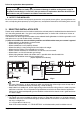
WHEN ELECTRIC WIRING WORK IS NOT FINISHED CAUTION • Electrical wiring work should be done by a certified electrician. • If someone who does not have the proper qualifications performs the work, perform the following after the test run is complete. • Remove the control box lid. Connect the single phase power supply (SINGLE PHASE 50Hz 220-240V, 60Hz 220V) to connections No.1 and No.2 on the terminal block for wiring the units. Do not connect to No.3 of the terminal block for wiring the units.
≥100 Drain pipe Plastic watering can (Tube should be about 100 mm long.) Service drain outlet (with rubber plug) (Use this outlet to drain water from the drain pan) [Method of adding water] Fig. 25 Terminal block for wiring the units Single phase power supply (50Hz 220-240V, 60Hz 220V) Control box lid Earth wire Earth terminal Fig. 26 CAUTION Drain piping connections Do not connect the drain piping directly to sewage pipes that smell of ammonia.
8. ELECTRIC WIRING WORK • Electric wiring work must be conducted by electrician authorized by power companies. (Only licensed electrician can conduct electric work and earth connections.) • All wiring must be performed by an authorized electrician. • A circuit breaker capable of shutting down power supply to the entire system must be installed. • Be sure to install an earth leakage circuit breaker to the outdoor unit.
• Protect the wire and the wiring through hole area for wirings [Processing method of wiring through hole] of the transmission, earth and the remote controller in order Wiring through hole to prevent the intrusion of water and small animals into the air conditioner after the system is wired. Transmission wire, • Halve the sealing pad - small (13), then wind round each one to earth wire or remote the respective wiring lines.
Precautions to be taken for power supply wiring Use a round crimp-style terminal for connection to the power supply terminal block. In case it cannot be used due to unavoidable reasons, be sure to observe the following instructions. (Refer to Fig. 29) • Do not connect wires of different gauge to the same power supply terminal. (Looseness in the connection may cause overheating.) (Refer to Fig. 30) • When connecting wires of the same gauge, connect them according to. (Refer to Fig.
Pair type Main power supply Main switch Fuse Outdoor unit 1 2 3 1 2 3 P1 P2 Indoor unit P1 P2 Remote controller (Optional accessory) Fig. 31 Standard wiring accessories Singlephase supply Model Earth wire (copper) FCQG71EVEB Indoor unit Connection pipe between indoor unit and outdoor unit Minimum thickness Length ≥2.0 mm2 φ1.6 2.0 mm φ1.
When implementing group control • When using as a pair unit or as a parent unit for simultaneous operation multi, you may simultaneous start/ stop (group) control up to 16 unit with the remote controller. • In this case, all the indoor units in the group will operate in accordance with the group control remote controller. Outdoor unit 1 Indoor unit (slave) Outdoor unit 2 Outdoor unit 16 Indoor unit 1 Group control remote controller Indoor unit 2 (master) Indoor unit 16 Fig.
Fig. 35 Upper part of remote controller Fig. 36 (Factory setting) Insert the screwdriver here and gently work off the upper part of remote controller. Lower part of remote controller (Only one remote controller needs to be changed if factory settings have remained untouched.) S M S M Remote controller PC board Wiring Method (See ‘‘8. ELECTRIC WIRING WORK’’) (3) Remove the control box lid (4) Add remote controller 2 (slave) to the terminal block for remote controller (P1, P2) in the control box.
Table 5 Ceiling height (m) FCQG100·125· FCQG71EVEB 140EVEB Standard-All round Less than 2.7 m Less than 3.2m More than 2.7 m; More than 3.2m; High ceiling 1 3.0 m or less 3.6m or less More than 3.0 m; More than 3.6m; High ceiling 2 3.5 m or less 4.2m or less Mode No. * FIRST CODE NO. SECOND CODE NO. Setting 01 13 (23) 0 02 03 NOTE 1. “Mode No.” setting is done in a batch for the group. To make or confirm settings for an individual unit, set the Mode No. shown in parentheses. 2.
NOTE 1. “Mode No.” setting is done in a batch for the group. To make or confirm settings for an individual unit, set the Mode No. shown in parentheses. 2. Make settings for “No display” in cases where no cleaning display is required, e.g., at the time of regular maintenance servicing. 11-5 Settings for Mounting Options • When installing an option sold separately, refer to the operation manual attached to the option. 12.
*After turning on the power, the maximum is 90 seconds, although it will only display “88”. This is not a problem, and it will be set for 90 seconds. ■ Trouble shooting with the display on the liquid crystal display remote controller. 1. With the wired remote controller. (NOTE 1) When the operation stops due to trouble, operation lamp flashed, and “ ” and the Malfunction code are indicated on the liquid crystal display.
12-3 Malfunction code list • For plases where the Malfunction code is left blank, the “ ” indication is not displayed. Though the system continues operating, be sure to inspect the system and make repairs as necessary. • Depending on the type of indoor or outdoor unit, the Malfunction code may or may not be displayed.
L5 L8 L9 LC P1 P3 P4 PJ U0 U1 U2 U4 UF U5 UA UE UC Instantaneous overcurrent (outdoor unit) Possible earth fault or short circuit in the compressor motor. Electric thermal (outdoor unit) Possible electrical overload in the compressor or cut line in the compressor motor. Stall prevention (outdoor unit) Compressor possibly locked.
Fig.
3P177351-3J EM10A017 (1008) FS