
Specifications

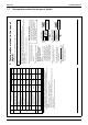

ED72-975 Installation Manual
BRC1E61 41
3P243521-1
8 English
Ɣ Perform wiring apart from a power line not to receive electrical noise (external noise)
during the wiring.
Seal wiring draw-in port securely with putty (fi eld supply) to prevent entry of insects or Ɣ
the like.
CAUTION
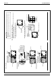
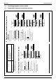
Fixing procedure of lower case.3-6
In the case of wiring center upward drawing or rearward drawing, see wiring procedure fi rst as
wiring with the case is needed before fi xing.
In the case of installation on the wall3-6-1
Secure by using attached wood screws (2 pcs.).
Wood screws
(F3.5×16)
In the case of installation on the switch box 3-6-2
Secure by using attached small screws (2 pcs.).
Small screws (M4×16)
Switch box
(field supply)
(Use optional accessory
KJB211A)
Switch box for two units
(with no cover)
84
46
(Installation pitch)
01_EN_3P243521-1.indd 8 2/3/2009 1:19:18 PM
English 7
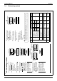
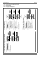
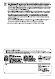
Left outlet3-5-2
PC-board
Lower case
Upper case
Indoor unit
P1P2
Ground the shielded
part on the indoor
unit side. (NOTE.1)
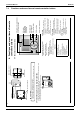
Upper outlet3-5-3
Install attached
wiring retainer to
prevent wiring pinch
according to left
figure.
PC-board
Indoor unit
Wiring retainer
Wiring retainer
Upper case
Lower case
Upper case
Wiring
Cross-section -
P1P2
Ground the
shielded part on
the indoor unit
side. (NOTE.1)
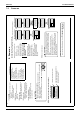
Upper center outlet3-5-4
PC-board
Indoor unit
Wiring retainer
Upper case
Lower case
P1P2
Ground the shielded
part on the indoor
unit side. (NOTE.1)
01_EN_3P243521-1.indd 7 2/3/2009 1:19:17 PM