
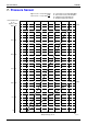
Specifications


Si38-606
Drawings & Flow Charts v
Drawings & Flow Charts
A
Abnormal Discharge Pipe Temperature................142
Abnormal Outdoor Fan Motor Signal ....................144
Actuation of High Pressure Switch........................134
Actuation of Low Pressure Sensor........................135
Additional refrigerant charge total flow....................99
Address Duplication of Centralized Remote
Controller .......................................................176
Address Duplication, Improper Setting......... 185
,
192
C
Centralized Control Group No. Setting
BRC1C Type ....................................................83
BRC4C Type ....................................................84
BRC7C Type ....................................................84
BRC7E Type.....................................................84
Group No. Setting Example..............................84
Check No. 12 ........................................................200
Check No. 8 ..........................................................199
Check No. 9 ..........................................................199
Check Operation .....................................................71
Check Operation not Executed .............................166
Check Work Prior to Turn Power Supply On...........70
Compressor Motor Lock........................................136
Current Sensor Malfunction ..................................146
D
Display “Under Centralized Control” Blinks
(Repeats Double Blink) ..................................198
Display “Under Centralized Control” Blinks
(Repeats Single Blink) ...................................195
Display of sensor and address data......................112
Drain Level above Limit.........................................127
Drain Pump Control.................................................62
When the Float Switch is Tripped and “AF” is
Displayed on the Remote Controller....63
When the Float Switch is Tripped During Heating
Operation .............................................63
When the Float Switch is Tripped while the
Cooling Thermostat is OFF..................62
When the Float Switch is Tripped while the
Cooling Thermostat is ON ...................62
E
Error of External Protection Device.......................118
Excessive Number of Indoor Units........................175
F
Fan Motor (M1F) Lock, Overload ..........................122
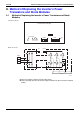
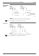
Field Setting from Outdoor Unit
Mode changing procedure................................88
Setting by pushbutton switches ........................87
Setting by dip switches .....................................87
Forced fan ON.......................................................112
Freeze Prevention...................................................67
Functional Parts Layout
RXM8, 10M...................................................... 40
H
How to Enter the Service Mode ........................... 111
I
Improper Combination of Optional Controllers for
Centralized Control ............................... 183
,
190
Individual setting .................................................. 112
Inverter Compressor Abnormal ............................ 154
Inverter Current Abnormal.................................... 155
Inverter Over-Ripple Protection............................ 159
Inverter Start up Error .......................................... 156
L
Louver Control for Preventing Ceiling Dirt.............. 64
Low Pressure Drop Due to Refrigerant Shortage or
Electronic Expansion Valve Failure............... 162
M
Malfunction hysteresis display ............................. 112
Malfunction of Capacity Determination Device..... 128
Malfunction of Discharge Pipe Thermistor
(R31 or 32T).................................................. 147
Malfunction of Drain Level Control System
(S1L, 33H)..................................................... 120
Malfunction of High Pressure Sensor................... 151
Malfunction of Inverter Radiating Fin Temperature
Rise ............................................................... 153
Malfunction of Inverter Radiating Fin Temperature
Rise Sensor................................................... 160
Malfunction of Low Pressure Sensor ................... 152
Malfunction of Moving Part of Electronic Expansion
Valve (20E) ................................................... 125
Malfunction of Moving Part of Electronic Expansion
Valve (Y1E, Y2E) .......................................... 140
Malfunction of Outdoor Unit Fan Motor ................ 138
Malfunction of Receiver Gas Pipe Thermistor
(R5T) ............................................................. 150
Malfunction of Swing Flap Motor (MA) ................. 123
Malfunction of System, Refrigerant System Address
Undefined...................................................... 180
Malfunction of Thermistor (R1T) for Suction Air ... 131
Malfunction of Thermistor (R2T) for
Heat Exchanger ............................................ 129
Malfunction of Thermistor (R2T) for
Suction Pipe .................................................. 148
Malfunction of Thermistor (R3T) for Gas Pipes.... 130
Malfunction of Thermistor (R4T) for Outdoor Unit
Heat Exchanger ............................................ 149
Malfunction of Thermistor for Outdoor Air (R1T) .. 145
Malfunction of Thermostat Sensor in Remote
Controller....................................................... 132