INSTALLATION MANUAL III SYSTEM Air Conditioners MODELS 〈BS unit〉 BSVQ36PVJU BSVQ60PVJU English Français READ THESE INSTRUCTIONS CAREFULLY BEFORE INSTALLATION. KEEP THIS MANUAL IN A HANDY PLACE FOR FUTURE REFERENCE.
BSVQ36PVJU BSVQ60PVJU VRVIII SYSTEM Air Conditioners Installation manual CONTENTS 1 2 3 4 5 6 7 8 9 SAFETY CONSIDERATIONS ........................................................................................ 1 BEFORE INSTALLATION .............................................................................................. 3 SELECTING INSTALLATION SITE ............................................................................... 5 PREPARATIONS BEFORE INSTALLATION....................................
• Do not ground units to water pipes, telephone wires or lightning rods because incomplete grounding could cause a severe shock hazard resulting in severe injury or death, and to gas pipes because a gas leak could result in an explosion which could lead to severe injury or death. • Safely dispose of the packing materials. Packing materials, such as nails and other metal or wooden parts, may cause stabs or other injuries.
• Be very careful about product transportation. Some products use PP bands for packaging. Do not use any PP bands for a means of transportation. It is dangerous. • Make sure to provide for adequate measures in order to prevent that the outside unit be used as a shelter by small animals. Small animals making contact with electrical parts can cause malfunctions, smoke or fire. Please instruct the customer to keep the area around the unit clean.
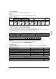
2-3 ACCESSORIES Check the following accessories are included with your unit. NOTE • Do not throw away any of the accessories until installation is complete. 〈BSVQ36 · 60PVJU〉 Name Quantity 1) Accessory pipes 1) Accessory pipes (BSVQ36 only) (BSVQ60 only) 1 pc. 1)-1 1 pc. 1)-2 1 pc. 2) Clamp 2 pcs. 1)-1 Explanation Document 3) Insulation tube 16 pcs. 2 pcs. 1)-2 1 pc. 3)-1 3)-2 2 pcs.
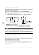
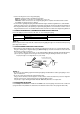
3. SELECTING INSTALLATION SITE Select an installation site where the following conditions are satisfied and that meets with your customer’s approval. • Where is resistible against weight of BS unit. • Locations where the wall is not significantly tilted. • Where sufficient clearance for maintenance and service can be ensured. (Refer to Fig. 1) • Locations where an inspection hole (Refer to Fig. 2) can be installed to EL. COMPO. BOX side (See Note).
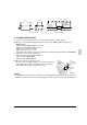
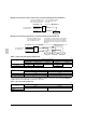
Anchor 16-7/8 8-5/8 Hanging bracket Unit proper 40 in. or less Long nut or turnbuckle Suspension bolt 40 in. or less Note: All the above parts are part to be procured in the field. Fig. 3 5. BS UNIT INSTALLATION Use only accessories and parts which are of the designated specification when installing. (1) When necessary, use the following procedure to change the EL. COMPO. BOX mounting surface. (Refer to Fig. 4) 1) Remove the EL. COMPO. BOX lid.
7) (Rotate 180 degrees) 3), 7) 3), 7) [Before change 5)-1] Top Panel (Rotate 180 degrees) 6) 3), 7) 4) 3), 7) 4), 6) 9) 8) 9) Coil cover EL. COMPO. BOX Remove the wire from the wire clip. 8) [After change 5)-3] EL. COMPO. BOX 2) 2) 1) 2) EL. COMPO. BOX lid EL. COMPO. BOX 1) Fig. 4 5)-2 (Move the EL. COMPO. BOX) Pass the wire through the wire clip. 6.
• Use the following items for the refrigerant piping. Material: Jointless phosphor-deoxidized copper pipe Size: See “Example of connection” to determine the correct size. Thickness: Select a thickness for the refrigerant piping which complies with national and local laws. For R410A, the design pressure is 478 psi.
Example of connection 1: When 1 indoor unit is connected downstream from the BS unit Determine using Table 1 based Select from Table 2 depending on the total capacity of the indoor on the capacity type of the units connected downstream. indoor unit.
6-5 PIPING CONNECTION Follow the connection example below and connect the site piping. BSVQ36P type When the downstream indoor unit total capacity is 36 or less and when one indoor unit with a capacity of 24 to 36 is connected downstream.
BSVQ36 · 60P type Insulation tube 3)-3 (Accessory) Clamp 2) (Accessory) Suction gas pipe (Note 1) HP/LP gas pipe (Note 1) Gas pipe (Note 1) BS unit Liquid pipe Liquid pipe Insulation tube 3)-2 (Accessory) Insulation tube 3)-1 (Accessory) Insulation Attachment Instructions (1) Attach the included insulation.
7-2 EXAMPLE FOR THE WHOLE SYSTEM Power supply Power supply wiring Outside unit Transmission wiring Main switch Switch Fuse Power supply Main switch BS unit Indoor unit Cooling-dedicated indoor unit Remote controller Cooling/Heating selectable indoor unit 7-3 POWER CIRCUIT, SAFETY DEVICE AND CABLE REQUIREMENTS • A power circuit (Refer to Table 3) must be provided for connection of the unit. This circuit must be protected with the required safety devices, i.e.
Absolutely do not connect the power supply wiring. Outside unit TO IN/D UNIT TO OUT/D UNIT Transmission wiring Use 2-core wires. (There is no polarity.) COOL/HEAT SELECTOR wiring Use 3-core wires. (There is polarity. Match the terminal numbers.
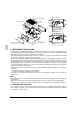
Wire Wire fitting Transmission wiring from the indoor unit (To the TO IN/D UNIT F1, F2 terminals) Ground terminal Ground wire Clamp 2) (Accessory) Clamp 2) (Accessory) A1P TO IN/D UNIT TO OUT/D UNIT F1 F2 F1 F2 Wiring through hole (left) Transmission wiring from the outside unit (To the TO OUT/D UNIT F1, F2 terminals) Terminal block Wiring through hole (right) Clamp 2) (Accessory) Power supply wiring (To the terminal block L1, L2 terminals) NOTES • Use ring-type crimp style terminal for connection
8. INITIAL SETTING • When the refrigerant piping and wire installation work is completed, make the following settings as required. 1. Setting for when connecting the COOL/HEAT SELECTOR to the BS unit. 〈Setting description〉 Set the input signal from the COOL/HEAT SELECTOR (sold separately) to ON/OFF. 〈Setting method〉 Set the dip switches (DS1-1) on PCB (A1P) as shown at left before turning on the power to the BS unit. Turn on DS1-1.
3P194121-3D EM07A062 (0712) FS HT