EDUS 39 - 900 - F8 BSVQ-P BS units AMERICAS 1645 Wallace Drive, Suite 110 Carrollton, TX75006 info@daikinac.com www.daikinac.com Specifications, designs and other content appearing in this brochure are current as of November 2009 but subject to change without notice. EDUS39-900-F8 Printed in U.S.A. 11/09 FS.
EDUS39-900-F8 BSVQ-P BS units 1. 2. 3. 4. 5. 6. 7. Specifications ..............................................................................................2 Dimensions .................................................................................................3 Piping diagrams ..........................................................................................6 Wiring diagrams ..........................................................................................
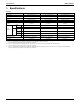
Specifications EDUS39-900-F8 1. Specifications BS units Model Power supply Total capacity index of connectable indoor unit No. of connectable indoor units Casing Dimensions: (H×W×D) in. Sound absorbing thermal insulation material Indoor unit BSVQ60PVJU BSVQ96PVJU 1 phase 60Hz 208~230V 1 phase 60Hz 208~230V Less than 36 Less than 60 Less than 96 Max. 5 Max. 8 Max.
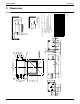
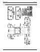
8-3/8 5-3/16 1-7/8 3 8-5/8 (Suspension bolt pitch) 12 (Servicing space) (4-5/16) 15-1/4 8 7 10 5 9 (4-5/16) 2-5/8 3/8 6 (Note 1.) Inspection door 18 (Note 2.
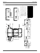
8-3/8 5-3/16 1-7/8 3 10 12 (Servicing space) (4-5/16) (8-5/8) 15-1/4 8 4 (4-5/16) ¨ 2-5/8 7 5 9 3/8 6 (Note 1.) Inspection door 18 (Note 2.) (8-9/16) Location of unit's Name Plate…Right side of electric box 8-1/8 (8-9/16) 7-9/16 2 16-7/8 (Suspension bolt pitch) 10-3/16 6-5/8 1-7/8 10 or more (Servicing space) Servicing space 3 or more (Servicing space) 13-3/4 or more (Servicing space) 10 or more (Servicing space) 10 9 8 7 6 5 4 3 2 1 Number Attached pipe (2) (Note.
EDUS39-900-F8 Dimensions an 3D065540 BSVQ96PVJU BSVQ-P 5
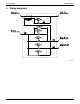
Piping diagrams EDUS39-900-F8 3.
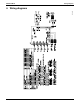
EDUS39-900-F8 Wiring diagrams 3D058235C 4.
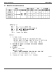
Electric characteristics EDUS39-900-F8 5.
EDUS39-900-F8 Safety devices setting 6. Safety devices setting Model BSVQ36PVJU BSVQ60PVJU BSVQ96PVJU PC board fuse 250V 3.15A 250V 3.15A 250V 3.
Sound levels EDUS39-900-F8 7. Sound levels 7.1 Overall Location of microphone Notes: 1. Operation noise differs with operation and ambient conditions. 2. In case of other unit operating in the same system, operating sound will be generated, ever if indoor unit connected to BS unit is stopped. 3. These sound levels are based on JIS standard and sound data are reference. dBA Model 7.
EDUS39-900-F8 Center of gravity 8.
Installation EDUS39-900-F8 9. Installation BSVQ36PVJU BSVQ60PVJU BSVQ96PVJU VRVIII SYSTEM Air Conditioners Installation manual CONTENTS 1 2 3 4 5 6 7 8 9 SAFETY CONSIDERATIONS ........................................................................................ 1 BEFORE INSTALLATION .............................................................................................. 4 SELECTING INSTALLATION SITE ...............................................................................
EDUS39-900-F8 Installation • After completing the installation work, check that the refrigerant gas does not leak throughout the system. • Do not install unit in an area where flammable materials are present due to risk of explosions that can cause serious injury or death. • Safely dispose all packing and transportation materials in accordance with federal/state/local laws or ordinances.
Installation EDUS39-900-F8 • Install drain piping to proper drainage. Improper drain piping may result in water leakage and property damage. • Insulate piping to prevent condensation. • Be careful when transporting the product. • Do not turn off the power immediately after stopping operation. Always wait for at least 5 minutes before turning off the power. Otherwise, water leakage may occur. • Do not use a charging cylinder. Using a charging cylinder may cause the refrigerant to deteriorate.
EDUS39-900-F8 Installation NOTE The refrigerant R410A requires strict cautions for keeping the system clean, dry and tight. A. Clean and dry Foreign materials (including mineral oils such as SUNISO oil or moisture) should be prevented from getting mixed into the system. B. Tight R410A does not contain any chlorine, does not destroy the ozone layer, and does not reduce the earth’s protection against harmful ultraviolet radiation. R410A can contribute slightly to the greenhouse effect if it is released.
Installation EDUS39-900-F8 2-4 COMBINATION • This BS unit is only applicable to VRV-III (REYQ__P) or VRV-WIII (RWEYQ__P) series equipment. It cannot be connected to older generation VRV systems (REYQ_M). • For series of applicable indoor units, refer to the catalog or other literature. • Select the BS unit to fit the total capacity (sum of unit’s capacity) and max. number of the indoor units to be connected downstream. About indoor unit’s capacity, refer to the Table 2.
EDUS39-900-F8 Installation Note: The Electrical Components Box mounting surface can be changed. For information on how to change the mounting surface, refer to “5. BS UNIT INSTALLATION”. (in.) 2-5/8 or more (in.) Outside unit side (3 pipes) BS unit proper top Indoor unit side (2 pipes) Electrical Components Box Inspection hole 18 Be sure to open this to the Electrical Components Box side. B 2 or more A Fig. 1 Fig. 2 (in.
Installation EDUS39-900-F8 5. BS UNIT INSTALLATION Use only accessories and parts which are of the designated specification when installing. (1) When necessary, use the following procedure to change the Electrical Components Box mounting surface. (Refer to Fig. 4) 1) Remove the Electrical Components Box lid. (2 screws) 2) Remove the Electrical Components Box. (2 screws) 3) Remove the top panel. (4 screws) 4) Remove the coil cover.
EDUS39-900-F8 Installation 6. REFRIGERANT PIPING WORK • For instruction for installing piping between the outside unit and BS unit, selecting a refrigerant branch kit, and installing piping between the refrigerant branch kit and the indoor unit, refer to the installation manual and equipment design materials included with the outside unit. • Before beginning the work, always check to make sure the type of refrigerant used is R410A. (The unit will not operate correctly with a different type of refrigerant.
Installation EDUS39-900-F8 6-3 PIPING CONNECTION WORK PRECAUTIONS • When brazing refrigerant piping, begin working after replacing the nitrogen (*1) or perform brazing while nitrogen is flowing in the refrigerant piping (*2) (Refer to Fig. 5), and at the end made the indoor unit and BS unit flare or flange connections. (*1) For details on nitrogen replacement, see the “VRV Installation Manual” (available at any Daikin dealer).
EDUS39-900-F8 Installation Table 1 Indoor unit total capacity and pipe size (in.) Piping size (outer diameter) Total capacity of indoor units (Q) Upstream Downstream Suction gas pipe HP/LP gas pipe Q < 54 I5/8 I1/2 54 d Q < 72 I3/4 I5/8 72 d Q d 96 I7/8 I3/4 Liquid pipe Gas pipe Liquid pipe I5/8 I3/8 I3/4 I3/8 I7/8 Table 2 Indoor unit connection pipe size (in.
Installation EDUS39-900-F8 BSVQ60P type When the downstream indoor unit total capacity is more than 36 but less than 54 and when one indoor unit with a capacity of 48 is connected downstream.
EDUS39-900-F8 Installation 6-6 PIPING INSULATION • After the gas leak inspection is completed, refer to the following figures and use the included insulation tube 3) and clamps 2)-2 to apply the insulation. NOTES • Insulate all of the piping including the liquid pipes, HP/LP gas pipes, suction gas pipes, gas pipes, and the pipe connections for these. Not insulating these pipes could result in water leaks or burns.
Installation EDUS39-900-F8 7. ELECTRIC WIRING WORK 7-1 GENERAL INSTRUCTIONS • • • • • • • • • • All wiring must be performed by an authorized electrician. All field supplied parts and materials, electric works must conform to local codes. Always ground wires. (In accordance with national regulations of the pertinent country.) Always turn off the power before performing the electric wire installation work. Follow the “WIRING DIAGRAM” attached to the unit body to wire the outside unit and indoor units.
EDUS39-900-F8 Installation Table 3 Units Power supply Model Type Hz Voltage Min. Max. MCA MFA BSVQ36P BSVQ60P BSVQ96P VJ 60 208~230 187 253 0.1 15 MCA: Min. Circuit Amps (A); MFA: Max. Fuse Amps (A) NOTES • The above Table 3 of Electrical Characteristics refers to one BS unit. • See the Engineering data book for other details. 7-4 WIRING EXAMPLE • Here is shown a wiring example for one system transmission wiring.
Installation EDUS39-900-F8 7-5 WIRING CONNECTIONS Remove the Electrical Components Box lid on the side and follow the directions to connect the wires. ¢Transmission wiring² Remove the Electrical Components Box lid and connect the wires to F1 and F2 (TO IN/D UNIT) and F1 and F2 (TO OUT/D UNIT) transmission wiring terminals (control PCB (A1P)). At this time, pass the wiring into the unit through the wiring through hole (left) and use the included clamps 2) to securely hold the wires (in 2 places).
EDUS39-900-F8 Installation NOTES • Use ring-type crimp style terminal for connections to the Insulation sleeve Ring-type crimp power terminal block. (Refer to Fig. 6) Electric wire style terminal Also, insulate the crimped area by attaching an insulation sleeve, etc. If these are not available, see the following section. Fig. 6 (a) Wiring of different thicknesses cannot be connected Connect wires of the Do not connect Do not connect to the power terminal block.
Installation EDUS39-900-F8 ¢Setting description² • The “Automatic mode differential” can be changed within the range of 0°F to 12.6°F (0°F at factory shipment). • For details regarding the “Automatic mode differential” and indoor unit operation, refer to the “Engineering data book”. ¢Setting method² The setting is made using the “Local Setting Mode” by the remote controller of indoor unit connected to the BS unit. For information regarding the setting method, refer to “Engineering data book”.
EDUS 39 - 900 - F8 BSVQ-P BS units AMERICAS 1645 Wallace Drive, Suite 110 Carrollton, TX75006 info@daikinac.com www.daikinac.com Specifications, designs and other content appearing in this brochure are current as of December 2009 but subject to change without notice. EDUS39-900-F8 Printed in U.S.A. 12/09 FS.