
Specifications
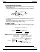
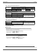
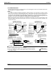
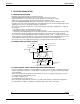
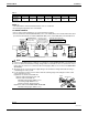

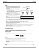
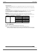

Table Of Contents

Installation EDUS39-900-F8
20 BSVQ-P
3P194121-3M
9 English
6-3 PIPING CONNECTION WORK PRECAUTIONS
• When brazing refrigerant piping, begin working after replacing the nitrogen (*1) or perform brazing while
nitrogen is flowing in the refrigerant piping (*2) (Refer to Fig. 5), and at the end made the indoor unit and
BS unit flare or flange connections.
(*1) For details on nitrogen replacement, see the “VRV Installation Manual” (available at any Daikin dealer).
(*2) The pressure regulator for the nitrogen released when doing the brazing should be set to about
2.9 psi (Enough to feel a slight breeze on your cheek).
NOTES
• Do not use an anti-oxidizing agent when brazing the piping. Residual debris could clog the piping or cause
parts to malfunction.
• Do not use a flux when brazing the refrigerant pipe joints.
Using a chlorine flux may cause the pipes to corrode, and if it contains fluoride it may cause the refrigerant
lubricant to deteriorate, adversely affecting the refrigerant piping system.
Use phosphor copper brazing (B-Cu93P-710/795: ISO 3677) which does not require flux.
6-4 PIPING SIZE SELECTION
From Example of connection 1 and 2 below and Table 1, 2, select the piping size between the outside unit
(refrigerant branch kit) and BS unit, and between the BS unit and the indoor unit (refrigerant branch kit).
Example of connection 1: When 1 indoor unit is connected downstream from the BS unit
Example of connection 2: When there is a branch downstream from the BS unit
Refrigerant piping
Valve
Pressure-reducing valve
Part to be brazed
Taping
Nitrogen
Nitrogen
Fig. 5
To refrigerant branch
kit or outside unit
*
Suction gas pipe
<Upstream> <Downstream>
Gas pipe
Indoor unit
Liquid pipe
HP/LP gas pipe
Liquid pipe
Determine using Table 1 based
on the total capacity of the indoor
units connected downstream.
Select from Table 2 depending
on the capacity type of the
indoor unit.
BS
unit
Indoor unit Indoor unit Indoor unit
Gas pipe
Liquid pipe
Determine using Table 1 based
on the total capacity of the indoor
units connected downstream.
For information on selecting the size of piping between
the refrigerant branch kits and between a refrigerant
branch kit and the indoor unit, refer to the Installation
Manual that came with the outside unit or Engineering
data book.
To refrigerant branch
kit or outside unit
Suction gas pipe
HP/LP gas pipe
Liquid pipe
BS
unit
Refrigerant branch kit
<Upstream> <Downstream>