English INSTALLATION MANUAL Deutsch DAIKIN ROOM AIR CONDITIONER FTXS20K3V1B FTXS25K3V1B CTXS15K3V1B CTXS35K3V1B ATXS20K3V1B ATXS25K3V1B Pyccкий FTXS20K2V1B FTXS25K2V1B CTXS15K2V1B CTXS35K2V1B ATXS20K2V1B ATXS25K2V1B Türkçe MODELS Portugues Eλληνικά Italiano Español Nederlands Français R410A Split Series
CE - DECLARACION-DE-CONFORMIDAD CE - DICHIARAZIONE-DI-CONFORMITA CE - ∆HΛΩΣΗ ΣΥΜΜΟΡΦΩΣΗΣ CE - ERKLÆRING OM-SAMSVAR CE - ILMOITUS-YHDENMUKAISUUDESTA CE - PROHLÁŠENÍ-O-SHODĚ 10 09 08 07 19 ob upoštevanju določb: 20 vastavalt nõuetele: 21 следвайки клаузите на: 22 laikantis nuostatų, pateikiamų: 23 ievērojot prasības, kas noteiktas: 24 održiavajúc ustanovenia: 25 bunun koşullarına uygun olarak: 07 ** 08 ** 09 ** 10 ** 11 ** 12 ** 11 Information * enligt och godkänts av enligt Certifikatet .
CE - DECLARACION-DE-CONFORMIDAD CE - DICHIARAZIONE-DI-CONFORMITA CE - ∆HΛΩΣΗ ΣΥΜΜΟΡΦΩΣΗΣ 10 09 08 07 19 ob upoštevanju določb: 20 vastavalt nõuetele: 21 следвайки клаузите на: 22 laikantis nuostatų, pateikiamų: 23 ievērojot prasības, kas noteiktas: 24 održiavajúc ustanovenia: 25 bunun koşullarına uygun olarak: 07 ** 08 ** 09 ** 10 ** 11 ** 12 ** 11 Information * enligt och godkänts av enligt Certifikatet .
FTXS20K2V1B, FTXS25K2V1B, CTXS15K2V1B, CTXS35K2V1B DAIKIN INDUSTRIES, LTD. 3SB65451-1 , , Shinri Sada Manager Quality Control Department Low Voltage 2006/95/EC Electromagnetic Compatibility 2004/108/EC * Umeda Center Bldg., 2-4-12, Nakazaki-Nishi, Kita-ku, Osaka, 530-8323 Japan 74736-KRQ/EMC97-4957 DEKRA Certification B.V. (NB0344) DAIKIN.TCF.
FTXS20K2V1B, FTXS25K2V1B, CTXS15K2V1B, CTXS35K2V1B 3SB65451-2 , , Shinri Sada Manager Quality Control Department Umeda Center Bldg.
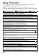
English Safety Precautions • The precautions described herein are classified as WARNING and CAUTION. They both contain important information regarding safety. Be sure to observe all precautions without fail. • Meaning of WARNING and CAUTION notices WARNING.....Failure to follow these instructions properly may result in personal injury or loss of life. CAUTION......
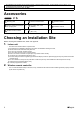
• This appliance is intended to be used by expert or trained users in shops, in light industry and on farms, or for commercial and household use by lay persons. • Sound pressure level is less than 70 dB(A). Accessories Indoor unit A – H A Mounting plate 1 D Remote controller holder 1 G Operation manual 1 B Titanium apatite photocatalytic air-purifying filter 2 E Dry battery AAA.
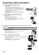
1. English Preparation before Installation Removing and installing front panel • Removal method 1) Place your fingers in the indentations on the main unit (one each on the left and right sides), and open the front panel until it stops. 2) Continue to open the front panel further while sliding the panel to the right and pulling it toward you in order to disengage the front panel shaft on the left side.
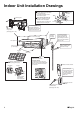
Indoor Unit Installation Drawings How to attach the indoor unit Hook the claws of the bottom frame to the mounting plate. If the claws are difficult to hook, remove the front grille. How to remove the indoor unit Push up the marked area (at the lower part of the front grille) to release the claws. If it is difficult to release, remove the front grille.
1. English Indoor Unit Installation Installing the mounting plate • The mounting plate should be installed on a wall which can support the weight of the indoor unit. 1) Temporarily secure the mounting plate to the wall, make sure that the panel is completely level, and mark the boring points on the wall. 2) Secure the mounting plate to the wall with screws. Recommended mounting plate retention spots and dimensions Recommended mounting plate retention spots (5 spots in all) 125.
Indoor Unit Installation • Remove the pipe port cover as shown below. 1) Cut off the pipe port cover from inside the front grille using a copping saw. Apply the blade of the copping saw to the notch, and cut off the pipe port cover along the slit. 2) After cutting off the pipe port cover, perform filing. Remove the burrs along the cut section using a half round needle file. CAUTION • If the pipe port cover is cut off using nippers, the front grille will be damaged. Please do not use nippers.
English Indoor Unit Installation 3-2. Left-side, left-back, or left-bottom piping How to replace the drain plug and drain hose • Replacing onto the left side Drain hose attachment position 1) Remove the insulation fixing screw on the right and remove the drain hose. 2) Remove the drain plug on the left side and attach it to the right side. 3) Insert the drain hose and tighten with included insulation fixing screw. * (Forgetting to tighten this may cause water leakages.
Indoor Unit Installation Wiring diagram : Terminal strip : Connection : Connector : Field wiring BLK : Black ORG : Orange BLU : Blue RED : Red BRN : Brown WHT : White GRN : Green YLW : Yellow Notes : Refer to the nameplate for power requirements.
4. English Indoor Unit Installation Wiring 1) Strip wire ends (15mm). 2) Match wire colours with terminal numbers on indoor and outdoor unit’s terminal blocks and firmly screw wires to the corresponding terminals. 3) Connect the earth wires to the corresponding terminals. 4) Pull wires to make sure that they are securely latched up, then retain wires with wire retainer. 5) Shape the wires so that the service lid fits securely, then close service lid.
Indoor Unit Installation 5-5. Prepare the accessory (optional parts) [Figure 2]. 1) Remove the cover from the accessory (optional parts). 2) Insert the connection cord into connector “S21” (white) in the accessory (optional parts). 3) Route each of the connection cords through the cut-outs in the accessory, then reinstall the accessory cover in its original position. 4) Insert the accessory (optional parts) connector into connector “S403” in the electrical component box.
6. Drain piping The drain hose should be inclined downward. 1) Connect the drain hose, as described right. No trap is permitted. Do not put the end of the hose in water. 2) Remove the air filters and pour some water into the drain pan to check the water flows smoothly. 3) If drain hose extension or embedded drain piping is required, use appropriate parts that match the hose front end.
Refrigerant Piping Work 2. Refrigerant piping CAUTION • Use the flare nut fixed to the main unit. (To prevent cracking of the flare nut by aged deterioration.) • To prevent gas leakage, apply refrigeration oil only to the inner surface of the flare. (Use refrigeration oil for R410A.) • Use torque wrenches when tightening the flare nuts to prevent damage to the flare nuts and gas leakage. Align the centres of both flares and tighten the flare nuts 3 or 4 turns by hand.
1. English Trial Operation and Testing Trial operation and testing 1-1 Measure the supply voltage and make sure that it falls in the specified range. 1-2 Trial operation should be carried out in either cooling or heating mode. • In cooling mode, select the lowest programmable temperature; in heating mode, select the highest programmable temperature. 1) Trial operation may be disabled in either mode depending on the room temperature. Use the remote controller for trial operation as described below.
3P363588-1B 2014.