
Installation Instructions


8 English
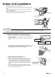
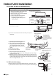
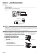
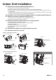
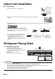
Indoor Unit Installation
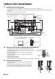
Wiring diagram
Wiring diagram parts table
: Terminal strip : Connection
: Connector : Field wiring
BLK : Black ORG : Orange
BLU : Blue RED : Red
BRN : Brown WHT : White
GRN : Green YLW : Yellow
Notes
: Refer to the nameplate for power requirements.
: INDOOR Indoor
: OUTDOOR Outdoor
: TRANSMISSION CIRCUIT Transmission circuit
: INTELLIGENT EYE SENSOR Intelligent eye sensor
: WIRELESS REMOTE CONTROLLER Wireless remote controller
: SIGNAL RECEIVER Signal receiver
BZ .......................... Buzzer
C101,C102............. Capacitor
FG.......................... Frame ground
F1U ........................ Fuse (3,15A)
H1P~H3P............... Pilot lamp
MR10 ..................... Magnetic relay
M1F........................ Fan motor
M1S~M3S.............. Swing motor
PCB1~PCB4.......... Printed circuit board
R1T,R2T................. Thermistor
S1~S49.................. Connector
SW1 ....................... Operation switch
V1 .......................... Varistor
X1M ....................... Terminal strip
....................... Protective earth
CAUTION
Note that operation will restart automatically if the
main power supply is turned off and then back on again.
HIGH VOLTAGE – be sure to discharge the capacitor completely
before repair work.
Risk of failure or water leakage! Do not wash the inside of the air
conditioner by yourself.