DAIKIN ROOM AIR CONDITIONER INSTALLATION MANUAL Deutsch English 00_CV_3P232706-1A.
CTXU25G2V1B, CTXU35G2V1B, CTXU42G2V1B, CTXU50G2V1B DAIKIN INDUSTRIES, LTD. Noboru Murata Manager Quality Control Department 1st. of Nov. 2008 Low Voltage 2006/95/EC Electromagnetic Compatibility 2004/108/EC * Umeda Center Bldg., 2-4-12, Nakazaki-Nishi, Kita-ku, Osaka, 530-8323 Japan 74736-KRQ/EMC97-4957 KEMA Quality B.V. DAIKIN.TCF.015 M7/10-2008 3SB64417-8C.
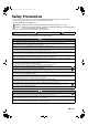
01_EN_3P232706-1A.fm Page 1 Friday, November 21, 2008 4:19 PM Safety Precautions • The precautions described herein are classified as WARNING and CAUTION. They both contain important information regarding safety. Be sure to observe all precautions without fail. • Meaning of WARNING and CAUTION notices WARNING .... Failure to follow these instructions properly may result in personal injury or loss of life. CAUTION .....
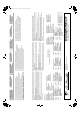
01_EN_3P232706-1A.fm Page 2 Friday, November 21, 2008 4:19 PM Indoor unit English Accessories A – K , A Mounting plate 1 E Wireless remote controller 1 J Operation manual 1 B Titanium apatite photocatalytic air-purifying filter (short) 1 F Remote controller holder 1 K Installation manual 1 C Titanium apatite photocatalytic air-purifying filter (long) 1 G Dry batteries AAA.
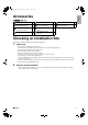
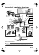
01_EN_3P232706-1A.fm Page 3 Friday, November 21, 2008 4:19 PM Indoor Unit Installation Drawings n How to attach the indoor unit. A Mounting plate Hook the claws of the bottom frame to the mounting plate. If the claws are difficult to hook, remove the front grille. A Mounting plate Clip n How to remove the indoor unit. Push up the marked area (at the lower part of the front grille) to release the claws. If it is difficult to release, remove the front grille.
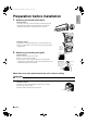
01_EN_3P232706-1A.fm Page 4 Friday, November 21, 2008 4:19 PM 1. English Preparation before Installation Removing and installing front panel. • Removal method Hook fingers on the tabs on the left and right of the main body, and open until the panel stops. Slide the front panel sideways to disengage the rotating shaft. Then pull the front panel toward you to remove it. • Installation method Align the tabs of the front panel with the grooves, and push all the way in. Then close slowly.
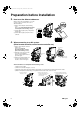
01_EN_3P232706-1A.fm Page 5 Friday, November 21, 2008 4:19 PM Preparation before Installation 3. How to set the different addresses. When 2 indoor units are installed in 1 room, the 2 wireless remote controllers can be set for different addresses. 1) Remove the metal plate electrical wiring cover. (Refer to the Removal/attachment methods of metal plate electrical wiring covers.) 2) Cut the address jumper (JA) on the printed circuit board. 3) Cut the address jumper (J4) in the remote controller.
English 01_EN_3P232706-1A.fm Page 6 Friday, November 21, 2008 4:19 PM • Attachment methods of metal plate electrical wiring covers Attach the metal plate electrical wiring covers as shown below. 1) Lean the metal plate electrical wiring cover as shown in the figure and attach tab (1) on the lower side to the electrical wiring box. 2) Attach tab (2) on the lower side of the metal plate electrical wiring cover.
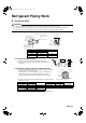
01_EN_3P232706-1A.fm Page 7 Friday, November 21, 2008 4:19 PM Refrigerant Piping Work 2. Refrigerant piping. CAUTION 1) Use the flare nut fixed to the main unit. (To prevent cracking of the flare nut by aged deterioration.) 2) To prevent gas leakage, apply refrigeration oil only to the inner surface of the flare. (Use refrigeration oil for R410A.) 3) Use torque wrenches when tightening the flare nuts to prevent damage to the flare nuts and gas leakage.
01_EN_3P232706-1A.fm Page 8 Friday, November 21, 2008 4:19 PM 1. English Indoor Unit Installation Installing the mounting plate. • The mounting plate should be installed on a wall which can support the weight of the indoor unit. 1) Temporarily secure the mounting plate to the wall, make sure that the panel is completely level, and mark the boring points on the wall. 2) Secure the mounting plate to the wall with screws.
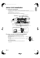
01_EN_3P232706-1A.fm Page 9 Friday, November 21, 2008 4:19 PM Indoor Unit Installation 3. Inter-unit wiring. 1) Open the front panel, then remove the service lid. 2) Pass the inter-unit wiring from the outdoor unit through the feed-through wall hole and then through the back of the indoor unit. Pull them through the front side. Bend the ends of tie wires upward for easier work in advance. (If the inter-unit wiring ends are to be stripped first, bundle wire ends with adhesive tape.
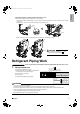
5. English 01_EN_3P232706-1A.fm Page 10 Friday, November 21, 2008 4:19 PM Laying piping, hoses, and wiring. • Connect the humidifying hose to the indoor unit duct. See 4. Humidifying hose installation work for details. • Lay the piping, drain hose and humidifying hose according to the orientation of the piping coming out of the unit, as shown below. • Make sure the drain hose is sloped downward. • Wrap the piping, drain hose and humidifying hose together using insulation tape.
01_EN_3P232706-1A.fm Page 11 Friday, November 21, 2008 4:19 PM Indoor Unit Installation • Left-side piping • Left-back piping • Left-bottom piping Humidifying hose Refrigerant pipe Drain hose Cut out the piping-through hole. Cut out the piping-through hole. Refrigerant pipe Refrigerant pipe Humidifying hose 1) Replace the drain plug and drain hose. (How to replace the drain plug and drain hose.
6. English 01_EN_3P232706-1A.fm Page 12 Friday, November 21, 2008 4:19 PM Wiring. With a multi indoor unit , install as described in the installation manual supplied with the multi outdoor unit. 1) Strip wire ends (15mm). 2) Match wire colours with terminal numbers on indoor and outdoor unit’s terminal blocks and firmly screw wires to the corresponding terminals. 3) Connect the earth wires to the corresponding terminals.
01_EN_3P232706-1A.fm Page 13 Friday, November 21, 2008 4:19 PM Setting the Humidifying Hose Length CAUTION If the humidifying hose length is not set or it is set incorrectly, the humidifying capacity may diminish or strange sound may occur from humidifying hose. 1. Setting the humidifying hose length. Set the humidifying hose length to ensure humidifying capacity. Use the remote controller to set the humidifying hose length.
01_EN_3P232706-1A.fm Page 14 Friday, November 21, 2008 4:19 PM 1. English Trial Operation and Testing Trial operation and testing. 1-1 Measure the supply voltage and make sure that it falls in the specified range. 1-2 Trial operation should be carried out in either cooling or heating mode. • In cooling mode, select the lowest programmable temperature; in heating mode, select the highest programmable temperature. 1) Trial operation may be disabled in either mode depending on the room temperature.
00_CV_3P232706-1A.fm Page 2 Friday, November 7, 2008 6:01 PM Two-dimensional bar code is a code for manufacturing.