00_CV_3P329626-1.
01_EN_3P329626-1.fm Page 1 Friday, November 9, 2012 11:10 AM Safety Precautions • Read these Safety Precautions carefully to ensure correct installation. • This manual classifies the precautions into DANGER, WARNING and CAUTION. Be sure to follow all the precautions below: they are all important for ensuring safety. DANGER ............Indicates an imminently hazardous situation which, if not avoided, will result in death or serious injury. WARNING ..........
01_EN_3P329626-1.fm Page 2 Friday, November 9, 2012 11:10 AM Safety Precautions WARNING • After connecting all wires be sure to shape the cables so that they do not put undue stress on the electrical covers, panels or terminals. Install covers over the wires. Incomplete cover installation may cause terminal overheating, electrical shock, fire or equipment damage.
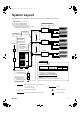
01_EN_3P329626-1.fm Page 3 Friday, November 9, 2012 11:10 AM System Layout For installation of the indoor and outdoor units, follow the instructions in the Installation manual for each unit. BP unit model For 3 rooms : BPMKS049A3U For 2 rooms : BPMKS048A2U Indoor unit side piping Choose the BP unit type (2 rooms or 3 rooms) according to the installation pattern.
01_EN_3P329626-1.fm Page 4 Friday, November 9, 2012 11:10 AM Accessories Installation Manual A F Conduit mounting plate (A) 1pc. Hanger metal B 1pc. G Conduit mounting plate (B) 4pcs. Screws: M4 (length: 5/16 inch) C 1pc. H Conduit mounting plate (cover) 16pcs. Reducer assembly D 2pcs. J Binding band 1set 6pcs. Heat insulation tape E 8pcs. (short) K 4pcs. (middle) Heat insulation (2pcs. is 1set) Total 16pcs. 4pcs.
01_EN_3P329626-1.
01_EN_3P329626-1.fm Page 6 Friday, November 9, 2012 11:10 AM Installation • This unit may be installed suspended from the ceiling or mounted on the wall. • Be sure to install the unit with the top surface facing upward as shown in the diagram. • Be sure to leave a 26 inch (650mm) square opening for maintenance and inspection as shown in the diagram below, for both ceiling-suspended installation and wall-mounted installation. • This unit “does not require drain treatment”.
01_EN_3P329626-1.fm Page 7 Friday, November 9, 2012 11:10 AM For 3 rooms (product dimensions and attachment bolt pitch) Suspension bolt pitch 12-11/16 (322) Suspension bolt pitch Wall-mounted 10 (254) (26-11/16 (678)) 1-3/4 (45) (12 (304)) Wire retainer 2-1/4 3-3/4 3-3/4 2-1/4 (57) (95) (95) (57) 7-9/16 (192) (11-9/16 (294)) Terminal block (for transmission) Room C Room B Room A 2-7/8 (73.5) 3-φ1/4 (φ6.4) flare connection 6-9/16 (167) φ5/8 (φ15.
01_EN_3P329626-1.fm Page 8 Friday, November 9, 2012 11:10 AM Installation of the Unit 1. Replacing the printed circuit board • This unit has 2 different installation types: (1) ceiling-suspended type and (2) wall-mounted type. • Choose the proper installation pattern according to the location of installation. • The installation location for the printed circuit board can be changed.
01_EN_3P329626-1.fm Page 9 Friday, November 9, 2012 11:10 AM 6) Attach the printed circuit board and electrical wiring box cover to the other side and secure with the screws. Printed circuit board Electrical wiring box cover Top surface of the unit Insert the tabs fully. 2. Ceiling-suspended type Procedure: B Hanger metal 0.59-0.79 (15-20) 1) Fix the furnished B hanger metal with two C screws. (4 locations in total) 2) Using an insert-hole-in-anchor, hang the hanging bolt.
01_EN_3P329626-1.fm Page 10 Friday, November 9, 2012 11:10 AM Connection of Refrigerant Piping
01_EN_3P329626-1.fm Page 11 Friday, November 9, 2012 11:10 AM How to use reducer No.1 f5/8 (f15.9) ® f1/2 (f12.7) No.2 f3/8 (f9.5) ® f1/4 (f6.4) No.3 No.4 f5/8 (f15.9) f3/8 (f9.5) ® f1/2 (f12.7) ® f1/4 (f6.4) No.5 f5/8 (f15.9) ® f3/8 (f9.5) Gasket (2) Gasket (1) No.6 f5/8 (f15.9) ® f3/8 (f9.5) Reduce and gasket Use the reducers supplied with the unit as described below. 1) Connecting a pipe of φ1/2 (φ12.7) to a gas pipe connection port for φ5/8 (φ15.9): Inter-unit pipe (B1/2 (B12.7)) No.
01_EN_3P329626-1.fm Page 12 Friday, November 9, 2012 11:10 AM Connection of Refrigerant Piping Gas leakage check • Perform gas leakage check after the completion of piping work. BP unit Outdoor unit side piping Indoor unit side piping Check the parts enclosed by for leakage. • Check carefully by applying soapy water. • Wipe soapy water thoroughly after checking.
01_EN_3P329626-1.fm Page 13 Friday, November 9, 2012 11:10 AM Connecting the Wiring Connection example of total system wiring Indoor unit BP unit Power Indoor unit 3 Indoor unit Wiring method for the power line.
01_EN_3P329626-1.fm Page 14 Friday, November 9, 2012 11:10 AM Connecting the Wiring 3) Install the conduit (field supply) and lock nut (field supply) to F conduit mounting plate (A) and G conduit mounting plate (B).
01_EN_3P329626-1.fm Page 15 Friday, November 9, 2012 11:10 AM 5) Follow the instructions on the wiring nameplate to connect the connection wires of indoor/outdoor units to terminal block numbers (1, 2, 3, F1 and F2). Always fix each ground wire separately with a ground screw. (See the figure below.) Example J Binding band J Binding band Secure the wires with J binding band to prevent them from coming out if pulled on from the outside.
01_EN_3P329626-1.fm Page 16 Friday, November 9, 2012 11:10 AM Connecting the Wiring 6) Return the electrical wiring box cover to its original position, and fix it with the screws. Screw (M4) Install the electrical wiring box cover. 7) Fix the H conduit mounting plate (cover) with the screw. C Screw (M4) H Conduit mounting plate (cover) Operating Test Follow the “Operating test” as described in the installation manual of the outdoor unit.
00_CV_3P329626-1.fm Page 2 Thursday, November 8, 2012 11:52 AM Two-dimensional bar code is a code for manufacturing.