
BPMKS048A2U Installation Manual


English 5
Installation
Piping length
Piping length
Pipe length between outdoor unit and first refrigerant branch kit (refnet joint) ≥ 16.4ft (5m)
[Example] a ≥ 16.4ft (5m)
[Example] unit 6: b+c+k ≤ 131ft (40m)
[Example] unit 5: b+e+j ≤ 131ft (40m)
[Example] unit 3: d+h ≤ 131ft (40m)
Piping length from first refrigerant branch kit (refnet joint) to indoor unit ≤ 131ft (40m)
Minimum allowable length
∗1
Since the sound of refrigerant may
be transferred from the outdoor unit
to the indoor unit, make the pipe
length from the outdoor unit to the
first junction 16.4ft (5m) or longer.
Allowable length after the branch
∗2 Branch kit are recommended to
set as possible as near the BP
units.
c, d, e are recommended to be
as possible as short.
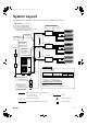
Example of connection
(Connection of 7 units heat pump system)
indoor unit
BP unit
refrigerant branch kit (refnet joint)
Branch with refnet joint
Pipe length between outdoor and BP units ≤ 180ft (55m)
[Example] a+b+c+d+e ≤ 180ft (55m)
Piping length between BP and indoor units ≤ 262ft (80m)
[Example] f+g+h+i+j+k+ ≤ 262ft (80m)
Piping length between BP and indoor unit ≤ 49ft (15m)
[Example] f, g, h, i, j, k, ≤ 49ft (15m)
Difference in height between outdoor and indoor units (H1) ≤ 98ft (30m)
Difference in height between outdoor and BP units (H2) ≤ 98ft (30m)
Difference in height between BP unit and BP units (H3) ≤ 49ft (15m)
Difference in height between indoor and indoor units (H4) ≤ 49ft (15m)
Refrigerant branch kit (refnet joint) name: KHRP26M22T
Maximum
allowable
length
Between indoor
and indoor units
Between BP and
BP units
Between outdoor
and BP units
Between outdoor
and indoor units
Between BP and
indoor unit
Between BP and
indoor units
Between outdoor
and BP units
Difference in height
Difference in height
Difference in height
Difference in height
1 room length
Total piping length
Total piping length
Allowable
height
Refrigerant branch kit selection
(refrigerant branch kits can only be used with R410A)
Piping size selection
a
12
BP
BP
3
45
6
d
fg
h
ij
k
e
bc
H1
H4
H2
H3
A
1
2
BP
3
B
7
1
A
BP 1
[Example]
indoor 1: 9000 Btu/h
indoor 2: 12000 Btu/h
indoor 3: 18000 Btu/h
=> (Gas pipe) φ5/8 × 0.039 (φ15.9 × 1.0) / (Liquid pipe) φ3/8 × 0.031 (φ9.5 × 0.8)
Qe = 39000 Btu/h
• Piping size (Outer diameter × minimum thickness) unit: inch (mm)
Between refrigerant branch
kit and BP unit
Between first refrigerant branch
kit and the other branch kit
Between outdoor unit and
first refrigerant branch kit
symbol
a
b
c, d, e
Gas pipe Liquid pipe
φ3/4 × 0.039
(φ19.1 × 1.0)
φ5/8 × 0.039
(φ15.9 × 1.0)
φ3/8 × 0.031
(φ9.5 × 0.8)
φ3/8 × 0.031
(φ9.5 × 0.8)
See the table A
Total indoor capacity Q
Qc, Qd, Qe ≤ 17000 Btu/h
Qc, Qd, Qe > 17000 Btu/h
Gas pipe Liquid pipe
φ1/2 × 0.031 (φ12.7 × 0.8)
φ5/8 × 0.039 (φ15.9 × 1.0)
φ1/4 × 0.031 (φ6.4 × 0.8)
φ3/8 × 0.031 (φ9.5 × 0.8)
Table A
∗Qc, Qd, Qe is total connected indoor capacity
∗Subscript c, d, e indicates the above symbol
01_EN_3P329626-1.fm Page 5 Friday, November 9, 2012 11:10 AM