
RMXS48LVJU Installation Manual

9 English
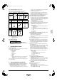
• When connecting the pipings downward, remove the knock-
out by making 4 holes in the middle on the each side of the
knockout with a drill.
(Refer to figure 22)
1. Dril
2. Center area around knockout hole
3. Knockout hole
4. Slit
• After knocking out the knock-out, it is recommended to apply
repair paint to the edge and the surrounding end surfaces to pre-
vent rusting.
(Refer to figure 23)
1. Bottom frame
2. Inter-unit piping
Note
Cutting out the 2 slits makes it possible to install as shown in fig-
ure 23. (Use a metal saw to cut out the slits.)
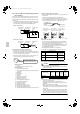
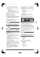
<Precautions when connecting pipes>
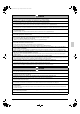
• Please refer to the Table 1 for the dimensions for processing
flares.
• When connecting the flare nut, coat the inner surface of the flare
with refrigeration oil and initially tighten by hand 3 or 4 turns
before tightening firmly.
• Please refer to the Table 1 for the tightening torque. (Too much
tightening will end up in splitting of the flare.)
Table 1
• If a torque wrench is not available, there is a place where the tight-
ening torque will suddenly increase if a normal wrench is used to
tighten the flare nut.
From that position, further tighten the flare nut the angle shown
below.
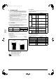
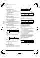
• After all the piping has been connected, use nitrogen to perform a
gas leak check.
(Refer to figure 24-[1])
1. Front connection
2. Gas side accessory pipe (1)
3. Gas side accessory pipe (3)
4. Gas side piping (field supply)
5. Cut at an appropriate length.
6. Gas side accessory pipe (2)
(Refer to figure 24-[2])
1. Rear-side connection
2. Gas side accessory pipe (1)
3. Gas side accessory pipe (2)
4. Gas side accessory pipe (3)
5. Gas side piping (field supply)
(Refer to figure 24-[3])
1. Side connection
2. Gas side accessory pipe (2)
3. Cut at an appropriate length.
4. Gas side piping (field supply)
5. Gas side accessory pipe (3)
6. Gas side accessory pipe (1)
(Refer to figure 24-[4])
1. Bottom connection
2. Cut at an appropriate length.
3. Gas side piping (field supply)
4. Gas side accessory pipe (3)
5. Gas side accessory pipe (1)
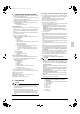
Precautions for connecting pipes
• Be careful not to let the inter-unit piping come into contact with the
compressor terminal cover.
Adjust the height of the insulation material on liquid pipe when it
has the possibility of getting in contact with the terminal. Also
make sure that the inter-unit piping does not touch the mounting
bolt of the compressor.
(Refer to figure 26)
1. Terminal cover
2. Compressor
3. Corking, etc.
4. Insulation material
5. Bolts
6. Inter-unit piping
• If installing the outdoor unit higher than the indoor unit, caulk the
space around insulation and tubes because condensation on the
check valve can seep through to the indoor unit side.
[Preventing foreign objects from entering]
• Plug the pipe through-holes with putty or insulating material (pro
cured locally) to stop up all gaps, as shown in figure 25.
(Insects or small animals entering the outdoor unit may cause a
short in the control box.)
(Refer to figure 25)
1. Putty or insulating material
2. (field supply)
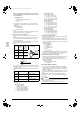
7-6 Heat insulation of piping
• If you think the humidity inside the ceiling might exceed 86°F
(30°C) and RH80%, reinforce the insulation on the cooling piping.
(At least 0.78 inch (20 mm) thick) (Condensation may form on the
surface of the insulation.)
• Be sure to insulate the inter-unit piping (liquid and gas-side) and
the refrigerant branch kit. (Not insulating them may cause leak-
ing.)
(The highest temperature that the gas-side piping can reach is
around 248°F (120°C), so be sure to use insulating material which is
very resistant.)
CAUTION
For local insulation, be sure to insulate all the way to the pipe con-
nections inside the machine.
Exposed piping may cause leaking or burns on contact.
Pipe size
Tightening
torque
A dimen-
sions for
processing
flares
Flare shape
φ
3/8 inch
(
φ
9.5mm)
24.1-29.4 ft·lbf
(32.7-39.9N·m)
0.504-0.520 inch
(12.8-13.2mm)
φ
5/8 inch
(
φ
15.9mm)
45.6-55.6 ft·lbf
(61.8-75.4N·m)
0.760-0.776 inch
(19.3-19.7mm)
φ
3/4 inch
(
φ
19.1mm)
71.7-87.5 ft·lbf
(97.2-118.6N·m)
0.929-0.944 inch
(23.6-24.0mm)
Pipe size Further tightening angle
Recommended arm length
of tool
φ
3/8 inch
(
φ
9.5mm)
60°- 90 °
Approx. 7-7/8 inch
(200 mm)
φ
5/8 inch
(
φ
15.9mm)
30°- 60°
Approx. 11-13/16 inch
(300 mm)
φ
3/4 inch
(
φ
19.1mm)
20° - 35°
Approx. 17-11/16 inch
(450 mm)
A
45˚± 2˚
90˚± 2˚
R0.016-0.031 inch
(R0.4-0.8mm)
Refrigeration oil
01_EN_3P329623-1.fm Page 9 Friday, November 9, 2012 6:50 PM