
RMXS48LVJU Installation Manual


English 10
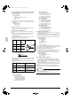
7-7 Example of connection
Example of connection
(Connection of 7 units heat pump system)
Branch with refnet joint
Maximum
allowable
length
Allowable length after the branch
∗2 Branch kit are recommanded to set as possible
as near the BP units.
c, d, e are recommanded to be as possible as short.
Between indoor and indoor units
Between BP and BP units
Between outdoor and BP units
Between outdoor and indoor units
Between BP and indoor unit
Between BP and indoor units
Between outdoor and BP units
Piping length
Piping length
Difference in height
Difference in height
Difference in height
Difference in height
1 room length
Total piping length
Total piping length
Pipe length between outdoor and BP units ≤ 180 ft (55m)
Pipe length between outdoor unit and first refrigerant branch kit (refnet joint) ≥ 16.4 ft (5m)
[Example] a ≥ 16.4 ft (5m)
Piping length between BP and indoor units: 262ft (80m)
[Example] a+b+c+d+e ≤ 180 ft (55m)
Piping length between BP and indoor unit ≤ 49 ft (15m)
Difference in height between outdoor and indoor units (H1) ≤ 98 ft (30m)
Difference in height between outdoor and BP units (H2) ≤ 98 ft (30m)
Difference in height between BP and BP units (H3) ≤ 49 ft (15m)
Refrigerant branch kit (refnet joint) name : KHRP26M22T
Difference in height between indoor and indoor units (H4) ≤ 49 ft (15m)
Piping length from first refrigerant branch kit (refnet joint) to indoor unit ≤ 131 ft (40m)
[Example] unit 6: b+c+k ≤ 131 ft (40m)
[Example] unit 5: b+e+j ≤ 131 ft (40m)
[Example] unit 3: d+h ≤ 131 ft (40m)
Allowable
height
Minimum allowable length
∗1 Since the sound of refrigerant may be transferred from
the outdoor unit to the indoor unit, make the pipe length
from the outdoor unit to the first junction 16.4 ft (5 m) or longer.
Refrigerant branch kit selection refrigerant branch kits can only be used with R410A
How to calculate the additional refrigerant to be charged
Additional refrigerant to be charged R (lb. /kg)
R should be rounded off in units of 0.1 lb. (0.1kg).
Pipe size selection
φ 1/2 × 0.031 (φ 12.7 × 0.8)
φ 5/8 × 0.039 (φ 15.9 × 1.0)
φ 1/4 × 0.031 (φ 6.4 × 0.8)
φ 3/4 × 0.039 (φ 19.1 × 1.0)
φ 5/8 × 0.031 (φ 15.9 × 1.0)
φ 3/8 × 0.031 (φ 9.5 × 0.8)
φ 3/8 × 0.031 (φ 9.5 × 0.8)
φ 3/8 × 0.031 (φ 9.5 × 0.8)
Table A
∗
Qc, Qd, Qe is total connected indoor capacity
[Example]
indoor 1: 9000 Btu/h
indoor 2: 12000 Btu/h
indoor 3: 18000 Btu/h
=>
(Gas pipe) φ5/8 × 0.031 (φ15.9 × 1.0) / (Liquid pipe) φ3/8 × 0.031 (φ9.5 × 0.8)
∗
c, d, e indicates the symbols in the figure
Gas pipe
Total indoor capacity Q
Liquid pipe
Qc, Qd, Qe ≤ 17000 Btu (5.0 kW)
Qc, Qd, Qe > 17000 Btu (5.0 kW)
• Piping size (Outer diameter × minimum thickness)
R=
+
Total length (ft / m)
of liquid piping size at
φ1/4 inch (φ6.4 mm)
×
0.015 lb./ft
(0.022 kg/m)
R=[(a+b+d+e)× ]+[(c+f+g+h+i+j+k+ )× ]=[ × ]+[ × ]=
0.036
(0.054)
0.015
(0.022)
0.036
(0.054)
0.015
(0.022)
8.118 → 8.1 lb.
(3.766 → 3.8kg)
234
(73)
128
(40)
×
0.036 lb./ft
(0.054 kg/m)
Total length (ft / m)
of liquid piping size at
φ3/8 inch (φ9.5 mm)
[Example] for refrigerant branch using refnet joint
unit : inch× ft (mm× m)
Between refrigerant branch kit and BP unit
Between refrigerant branch kit and refrigerant branch kit
Between outdoor unit and first refrigerant branch kit a
symbol Gas pipe Liquid pipe
b
c, d, e See the table A
indoor unit
BP unit
refrigerant branch kit (refnet joint)
Qd = 39000 Btu/h
BP
A
1
1
a
12
BP
BP
3
45
6
d
fg
h
ij
k
e
bc
H1
H4
H2
H3
A
1
2
BP
3
B
7
[Example] f+g+h+i+j+k+ ≤ 262ft (80m)
[Example] f, g, h, i, j, k, ≤ 49 ft (15m)
a:
φ
3/8 × 32 (
φ
9.5 × 10)
b:
φ
3/8 × 32 (
φ
9.5 × 10)
c:
φ
1/4 × 32 (
φ
6.4 × 10)
d:
φ
3/8 × 32 (
φ
9.5 × 10)
e:
φ
3/8 × 32 (
φ
9.5 × 10)
f :
φ
1/4 × 32 (
φ
6.4 × 10)
g:
φ
1/4 × 32 (
φ
6.4 × 10)
h:
φ
1/4 × 32 (
φ
6.4 × 10)
i :
φ
1/4 × 32 (
φ
6.4 × 10)
j :
φ
1/4 × 32 (
φ
6.4 × 10)
k:
φ
1/4 × 16 (
φ
6.4 × 5)
:
φ
1/4 × 26 (
φ
6.4 × 8)
unit : inch (mm)
01_EN_3P329623-1.fm Page 10 Friday, November 9, 2012 6:50 PM