
RMXS48LVJU Installation Manual


11 English
7-8 Air tight test and vacuum drying
After doing the piping, perform the following inspections.
Be sure to use nitrogen gas. (See the figure (“Stop valve operation
procedure”) for the location of the service port.)
[Procedure]
Pressurize from the liquid pipes and gas pipes to 478 PSI (3.3 MPa)
(and not above 478 PSI (3.3 MPa)). If there is not pressure drop over
the next 24 hours, the equipment has passed the test.
If the pressure drops, check for leakage positions. (Confirm that there
is no leakage, then release nitrogen.)
Use a vacuum pump that can create a vacuum down to at least
–14.6 PSI (–100.7 kPa).
[Procedure]
Operate the vacuum pump for at least 2 hours from both the liquid
and gas pipes and decrease the pressure to at least –14.6 PSI
(–100.7 kPa).
Leave at below –14.6 PSI (–100.7 kPa) for at least 1 hour and make
sure that the vacuum gauge does not rise. (If it does rise, there is
either still moisture in the system or a leak.)
Cases where moisture might enter the piping (i.e., if doing work
during the rainy season, if the actual work takes long enough that
condensation may form on the inside of the pipes, if rain might enter
the pipes during work, etc.)
After performing the vacuum drying for 2 hours, pressurize to
7.2 PSI (0.05 MPa) (i.e., vacuum breakdown) with nitrogen gas, then
depressurize down to at least –14.6 PSI (–100.7 kPa) for an hour
using the vacuum pump (vacuum drying). (If the pressure does not
reach at least –14.6 PSI (–100.7 kPa) even after depressurizing for at
least 2 hours, repeat the vacuum breakdown - vacuum drying pro-
cess.) Leave as a vacuum for 1 hour after that, and make sure the
vacuum gauge does not rise.
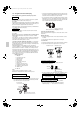
(Refer to figure 27)
1. Nitrogen
2. Decompression valve
3. Vacuum pump
4. Valve (open)
5. Charge hose
6. Stop valve service port
7. Indoor unit
8. Gas line stop valve (close)
9. Liquid line stop valve (close)
10. Indicates local procurement
11. Outdoor unit
12. BP unit
Note
The stop valve must always be turned to “closed”.
Otherwise the refrigerant in the outdoor unit will pour out.
• The names of parts needed to operate the stop valve are shown
in the figure below. The unit is shipped from the factory with the
stop valve turned to the “closed” position.
• Since the side boards may be deformed if only a torque wrench is
used when loosening or tightening flare nuts, always lock the stop
valve with a wrench and then use a torque wrench.
• In cases where the unit is run in heating mode when the outside
temperature is low or in other situations where the operating pres-
sure might drop, seal the gas-side flare nut on the stop valve with
silicon sealant or the like to prevent it from freezing.
Stop valve operation procedure
Have a hexagonal wrench ready (size: 0.2 inch and 0.3 inch / 4 mm
and 6 mm).
Opening the valve
1.
Place the hexagonal wrench on the valve bar and turn counter-
clockwise.
2.
Stop when the valve bar no longer turns. It is now open.
Close the valve
1.
Place the hexagonal wrench on the valve bar and turn clockwise.
2.
Stop when the valve bar no longer turns. It is now closed.
• A seal is attached to the point indicated by the arrow.
Take care not to damage it.
• Be sure to tighten the valve lid securely after operating the valves.
• Use a push-rod-provided charging hose for operation.
• Be sure to tighten the valve lid securely after operation.
Tightening torque .......... 8.5-10.3 ft·lbf (11.5-14.0 N·m)
Air tight test
Vacuum drying
Stop valve operation procedure
Precautions when handling the stop valve
Servicing port
Valve bar
Valve lid
Inter-unit piping connection
Precautions for handling valve lid
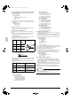
Liquid-side tightening torque Gas-side tightening torque
10.0-12.2 ft·lbf
(13.5-16.5 N·m)
16.6-20.3 ft·lbf
(22.5-27.5 N·m)
Precautions for handling servicing port
Silicon sealing pad
(Make sure that there is no gap)
Direction to open Direction to open
<Gas pipe><Liquid pipe>
Valve lid
Stop valve
(lid attachment)
01_EN_3P329623-1.fm Page 11 Friday, November 9, 2012 6:50 PM