
RMXS48LVJU Installation Manual


English 12
8. ADDITIONAL REFRIGERANT CHARGE
WARNING
• When leaving the unit with the power on, be sure to
switch with another person doing the installation or
close the front panel.
8-1 Before adding refrigerant
• Make sure the following work and inspection is complete, in
accordance with the installation manual.
•Piping
• Wiring
• Airtightness test, Vacuum drying
8-2 Checking the refrigerant tank
• Check whether the tank has a siphon pipe before charging and
place the tank so that the refrigerant is charged in liquid form.
(See the figure below.)
8-3 Adding refrigerant
1.
Calculate the amount of refrigerant to add as described in “Calcu-
lating the amount of refrigerant to add” in “7-7 Example of con-
nection (page 10)”.
2.
After the vacuum drying is finished, open valve A and charge the
calculated amount of refrigerant through the service port for the
liquid-side stop valve.
3.
Close valve A after charging is complete.
Note:If all the refrigerant to be added cannot be charged using the
above procedure, right-hand the procedure below and re-
charge the refrigerant.
If all the refrigerant could not be added
Add refrigerant using the following procedure. See the “Cautions on
Service” plate on the back of the front panel for details on the set-
tings for adding refrigerant.
[Procedure]
1.
Close the front panel and turn on the power to all outdoor units
and indoor units in the refrigeration system.
2.
Open the gas and liquid-side stop valve all the way and add the
refrigerant. (Open valve A immediately after starting the compres-
sor.)
3.
Once the appropriate amount of refrigerant is in, press the confir-
mation button (BS3) on the outdoor unit PC board (A2P), and stop
operation after adding the refrigerant.
4.
Close valve A after charging is complete.
9. POST-WORK CHECKS
Perform the following checks after work is complete.
(1) Drain pipe connection, removal of transport clasp →
See “5. PRECAUTIONS ON INSTALLATION (page 6)”.
(2) Incorrect power supply wiring, loose screws →
See “6-3 How to connect the power supply wiring (page 7)”.
(3) Incorrect inter-unit wiring, loose screws →
See “6-4 Inter-unit wiring connection procedure (page 8)”.
(4) Incorrect refrigerant piping connections →
See “7. PRECAUTIONS ON REFRIGERANT PIPING (page 8)”.
(5) Piping sizes, use of insulation →
See : “7-2 Selecting piping material (page 8)”.
“7-6 Heat insulation of piping (page 9)”.
(6) Stop valve check →
Make sure both the liquid-side and gas-side stop valves are
open.
(7) Record of Amount of Refrigerant Added →
Record it on “Recording the additionally charged refrigerant
quantity” on the “Cautions on Service” plate.
(8) Measuring the insulation of the main power circuit →
• Use a 500V mega-tester.
• Do not use the mega-tester for weak currents other than 208/
230V. (Inter-unit wiring)
CAUTION
To the pipe-layer
After completing installation, be sure to open the valve.
(Operating the unit with the valve shut will break the compressor.)
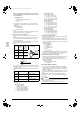
Filling after calculating the amount of refrigerant to add
Status of the stop valve and other valves when adding refrigerant
•
See “Stop valve operation procedure” in “7-8 Air tight test and
vacuum drying (page 11)” for details on how to use the stop valve.
(Refer to figure 28)
1. R410A Tank (Siphon system) 5. Stop valve service port
2. Measuring instrument 6. Gas line stop valve
3. Valve A 7.Outdoor unit
4. BP unit 8.Liquid line stop valve
State of valve A and the stop
valve
Valve A
Liquid line
stop valve
Gas line
stop valve
Before starting to charge the
refrigerant
Close Close Close
During charging of the refrig-
erant
Open Close Close
Location of “Cautions on Service” plate.
The back of front panel
Front panel
Tank with siphon pipe Other tanks
There is a siphon
pipe inside, so the
cylinder need not be
upside-down to fill
with liquid.
(Stand the cylinder
upright when filling.)
Stand the tank
upside down and
charge.
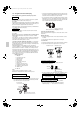
Status of the stop valve and other valves when adding refrigerant
operation
• See “Stop valve operation procedure” in “7-8 Air tight test and
vacuum drying (page 11)” for details on how to use the stop
valve.
• Connect the service port (for charging refrigerant) inside the
unit. When the unit is shipped from the factory, refrigerant is
already charged, so be careful when connecting the charge
hose.
• After adding the refrigerant, do not forget to close the lid of the
service port (for adding refrigerant). The tightening torque of the
lid is 8.5-10.3 ft·lbf (11.5-14.0 N·m)
(Refer to figure 29)
1. Gas line stop valve 2. Liquid line stop valve
3. Stop valve service port 4. BP unit
5. Measuring instrument 6. R410A Tank (Siphon
system)
7. Valve A 8. Service port
9.(For adding refrigerant) 10.Outdoor unit
State of valve A and the stop
valve
Valve A
Liquid line
stop valve
Gas line
stop valve
Before starting to charge the
refrigerant
Close Open Open
During charging of the refrig-
erant
Open Open Open
01_EN_3P329623-1.fm Page 12 Friday, November 9, 2012 6:50 PM