
RMXS48LVJU Installation Manual


13 English
10. TEST RUN
This unit is equipped with a crank case heater to ensure smooth
startup. Be sure to turn the power on at least 6 hours before
operation in order to have power running to the crank case
heater.
WARNING
When leaving the unit with the power on, be sure to
switch with another person doing the installation or
close the front panel.
Precautions before turning the power on
• Using insulating sheets, tape electric parts as described in the
“Cautions on Service” plate on the back of the front panel.
• All indoor units connected to the outdoor unit operate automati-
cally.
Complete work on the indoor units in order to ensure maximum
safety.
10-1 Power On–Check Operation
• Make sure to perform the check operation after installation.
(If the air conditioner is operated using the indoor remote control-
ler without performing the check operation, the malfunction code
“U3” is displayed in the indoor remote controller, and normal oper-
ation is disabled.)
• When making settings on the outdoor unit PC board (A2P) after
turning the power on, do not touch anything other than the push-
button switches and dip switches.
(See the “Cautions on Service” plate for the locations of the
push-button switches (BS1-5) and dip switches (D1-1, 2) on the
PC board (A2P).)
• During the operation, monitor the outdoor unit operation status
and check for any incorrect wiring.
<Precautions During Check Operation>
• If operation is performed within 12 minutes of BP units and
outdoor units being turned on, H2P will light up, and the
compressor will not run.
Only perform operation after checking that the LED display is as
shown in “10-1 Power On–Check Operation” 2. table.
• In order to ensure uniform refrigerant distribution, it may take up to
around 10 minutes for the compressor to start up after the unit
begins running. This is not a malfunction.
• Each indoor unit cannot be checked individually for problems.
After this operation is complete, run the unit normally using the
remote controller.
• The check run cannot be performed in recovery or other modes.
• If the outlet pipe thermistor (R2T), the intake pipe thermistor
(R3T), and the pressure sensors (S1NPH and S1NPL) are
removed before operation, the compressor might burn out, so
avoid this under all circumstances.
10-2 Temperature control operation checklist
• After check operation is complete, checking the temperature con-
trol using normal operation.
(Heating is not possible if the outdoor temperature is 75°F (24°C)
or higher. See the included operation manual.)
(1) Make sure the indoor and outdoor units are operating nor-
mally.
(If liquid compression by the compressor or other abnormal
noises can be heard, stop the unit immediately, heat the
crank case for a sufficient amount of time, and try again.)
(2) Run each indoor unit one at a time and make sure the corre-
sponding outdoor unit is also running.
(3) Check to see if cold (or hot) air is coming out of the indoor
unit.
(4) Press the fan direction and fan strength buttons on the indoor
unit to see if they operate properly.
<Precautions during temperature control checks>
• For around 5 minutes after the compressor stops, the compressor
will not run even if the “operate/stop” button on the remote control-
ler is pressed.
• When the system operation is stopped by the remote controller,
the outdoor units may continue operating for further 1 minutes at
maximum.
• Malfunction code “U3” is displayed if check operation is not per-
formed using the test run button the first time after installation.
Perform the check operation in accordance with “10-1 Power On–
Check Operation”.
[Indoor unit displays malfunction sign]
(Check on a remote controller connected to the indoor unit.
For details. see the operation manual which comes with indoor unit.
)
1. Close the outdoor unit’s front panel.
Turn the power on for the outdoor
unit and the BP unit.
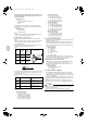
2.
•
Open the outdoor unit’s front panel.
•
Make sure the LED display on the outdoor unit’s PC boards (A1P and
A2P) are as shown in the following chart.
LED display
(Default status
before delivery)
SEVICE
MONITOR
MODE
HAP
A1P A2P
H1P H2P H3P H4P H5P H6P H7P
TEST/
HWL
IND
MASTER
SLAVE
L.N.O.P
DEMAND
6. Close the outer panel of the outdoor unit after check operation is complete.
Do not leave any stop valve closed
otherwise the compressor will fail.
Caution
Be sure to turn the power on at least
6 hours before operation in order to have
power running to the crank case heater.
To avoid the risk of electric shock, do not touch anything other than the
push-button switches on the PC board (A2P) when making settings.
Caution
LED display: OFF ON Blinking
Use caution to avoid electric shock while
working, since the outdoor unit is on.
•
Only set the push-button switches (BS1-5)
after making sure the microcomputer OK
monitor is lit up.
•
See the “Cautions on Service” plate on the
front panel of the outdoor unit for details on
how to make the settings.
(Do not forget to write the settings down on
the “Cautions on Service” plate.)
•
The dip switch (DS1-1) does not need to be
set, so do not touch it.
Doing so may cause malfunction.
• If you have to leave the outdoor unit during
check operation, either switch with another
worker or close the front panel.
• The system operates for about 30 minutes (60
minutes at maximum) and automatically stops
the check operation.
• The system can start normal operation about
3 minutes after the check operation if the
remote controller does not display any error
code.
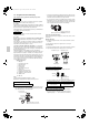
3.
•
When the customer requests
quiet operation or demand
operation, make these settings
using the push-button switches
(BS1-5) on the outdoor unit’s
PC board (A2P).
•
Operate the push-button
switches through the opening
after protecting it with an
insulation cover.
(See the “Cautions on Service”
plate for details.)
4.
•
Check that the liquid and gas-side
stop valves are open, and if
they are closed, open them.
5. Press the test run button (BS4) for
at least 5 seconds and perform
check operation.
For details, see “check operation
procedure” on the “Cautions on
Service” plate.
Malfunc-
tion code
Installation error Remedial action
E3
The stop valve of an out-
door unit is left closed.
Open the gas-side stop valve and the
liquid-side stop valve.
Refrigerant overcharge.
Recalculate the required amount of
refrigerant from the piping length and
correct the refrigerant charge level by
recovering any excessive refrigerant
with a refrigerant recovery machine.
E4
The stop valve of an out-
door unit is left closed.
Open the gas-side stop valve and the
liquid-side stop valve.
Insufficient refrigerant.
Check if the additional refrigerant
charge has been finished correctly.
Recalculate the required amount of
refrigerant from the piping length and
add an adequate amount of refrigerant.
F3
Refrigerant overcharge.
Recalculate the required amount of
refrigerant from the piping length and
correct the refrigerant charge level by
recovering any excessive refrigerant
with a refrigerant recovery machine.
The stop valve of an outdoor
unit is left closed.
Open the gas-side stop valve and the
liquid-side stop valve.
Insufficient refrigerant.
Check if the additional refrigerant
charge has been finished correctly.
Recalculate the required amount of
refrigerant from the piping length and
add an adequate amount of refrigerant.
01_EN_3P329623-1.fm Page 13 Friday, November 9, 2012 6:50 PM