
RMXS48LVJU Installation Manual


English 14
• When using a central controller, see the installation manual or
service manual which came with the central controller.
CAUTION
To the pipe-layer, To the electrician
After the test run, when handing the unit over to the customer,
make sure the front panel on the unit and all screws are attached.
11. CAUTION FOR REFRIGERANT LEAKS
(Points to note in connection with refrigerant leaks)
Introduction
The installer and system specialist shall secure safety against
leakage according to local regulations or standards. The follow-
ing standards may be applicable if local regulations are not
available.
This system uses R410A as refrigerant. R410A itself is an entirely
safe non-toxic, non-combustible refrigerant. Nevertheless care must
be taken to ensure that air conditioning facilities are installed in a
room which is sufficiently large. This assures that the maximum con-
centration level of refrigerant gas is not exceeded, in the unlikely
event of major leak in the system and this in accordance to the local
applicable regulations and standards.
Maximum concentration level
The maximum charge of refrigerant and the calculation of the maxi-
mum concentration of refrigerant is directly related to the humanly
occupied space in to which it could leak.
The unit of measurement of the concentration is lb./ft
3
(kg/m
3
) (the
weight in lb. (kg) of the refrigerant gas in 1 ft
3
(0.028 m
3
) volume of the
occupied space).
Compliance to the local applicable regulations and standards for the
maximum allowable concentration level is required.
Pay a special attention to the place, such as a basement, etc.
where refrigerant can stay, since refrigerant is heavier than air.
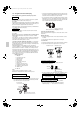
Procedure for checking maximum concentration
Check the maximum concentration level in accordance with steps 1
to 4 below and take whatever action is necessary to comply.
1. Calculate the amount of refrigerant (lb. / kg) charged to each sys-
tem separately.
Note
• Where a single refrigerant facility is divided into 2 entirely inde-
pendent refrigerant systems then use the amount of refrigerant
with which each separate system is charged.
2. Calculate the smallest room volume (ft
3
/m
3
)
Incase like the following, calculate the volume of (A), (B) as a sin-
gle room or as the smallest room.
A.
Where there are no smaller room divisions
B.
Where there is a room division but there is an opening
between the rooms sufficiently large to permit a free flow of
air back and forth.
(Where there is an opening without a door or where there are
openings above and below the door which are each equivalent in
size to 0.15% or more of the floor area.)
3. Calculating the refrigerant density using the results of the calcu-
lations in steps 1 and 2 above.
If the result of the above calculation exceeds the maximum con-
centration level then make similar calculations for the second then
third smallest room and so until the result falls short of the maxi-
mum concentration.
4. Dealing with the situations where the result exceeds the maxi-
mum concentration level.
Where the installation of a facility results in a concentration in
excess of the maximum concentration level then it will be neces-
sary to revise the system.
Please consult your Daikin supplier.
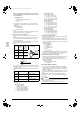
U2
Insufficient supply voltage
Check to see if the supply voltage is
supplied properly.
U3
If a check operation has not
been performed.
Perform a check operation.
U4
No power is supplied to an
outdoor unit.
Turn the power on for the outdoor unit.
UA
If no dedicated indoor unit is
being used.
Check the indoor unit. If it is not a ded-
icated unit, replace the indoor unit.
UF
The stop valve of an out-
door unit is left closed.
Open the gas-side stop valve and the
liquid-side stop valve.
If the right indoor unit piping
and wiring are not properly
connected to the outdoor
unit.
Make sure that the right indoor unit
piping and wiring are properly con-
nected to the outdoor unit.
UH
If the inter-unit wiring has
not be connected or it has
shorted.
Make sure the inter-unit wiring is cor-
rectly attached to terminals (X2M) F1/
F2 (To BP unit) on the outdoor unit cir-
cuit board.
Direction of the refrigerant flow
BP unit
Room where
refrigerant leak
has occurred
(outflow of all the
refrigerant from
the system)
amount of refriger-
ant in a single unit
system (amount of
refrigerant with
which the system
is charged before
leaving the factory)
+
additional charging
amount (amount of
refrigerant added
locally in accordance
with the length or
diameter of the refrig-
erant piping)
=
total amount
of refriger-
ant (lb. / kg)
in the system
total volume of refrigerant in the
refrigerant system
≤
maximum concen-
tration level (lb./ft
3
/
kg/m
3
)
size (ft
3
/ m
3
) of smallest room in
which there is an indoor unit
installed
BP unit
Opening
between rooms
Partition
BP unit
01_EN_3P329623-1.fm Page 14 Friday, November 9, 2012 6:50 PM