
RMXS48LVJU Installation Manual

English 4
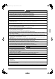
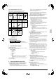
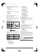
2-5 Standard supplied accessories
Make sure that the accessories shown below are all present.
(The accessories can be found behind the front panel.)
(Refer to figure 30)
1. Accessories
2. Screw for front panel
3. Front panel
2-6 Option accessory
• Refrigerant branching kit
* See “7. PRECAUTIONS ON REFRIGERANT PIPING” for
details on how to connect refrigerant branch kits and how many
are needed.
3. BEFORE INSTALLATION
<Transporting the Unit>
As shown in figure 2, bring the unit slowly. (Take care not to let hands
or things come in contact with rear fins.)
(Refer to figure 2)
1. Air outlet grille
2. Intake hole
3. Corner
4. Outdoor unit
5. Handle
6. Front
7. Rear
8. Always hold the unit by the corners, as holding it by the
side intake holes on the casing may cause them to
deform.
Use only accessories and parts which are of the designated specifi-
cation when installing.
4. SELECTING INSTALLATION SITE
(1) Select an installation site where the following conditions are
satisfied and that meets with your customer’s approval.
• Places which are well-ventilated.
• Places where the unit does not bother next-door neighbors.
• A locations where small animals will not make nests in the unit.
• Safe places which can withstand the unit’s weight and vibration
and where the unit can be installed level.
• Locations not exposed to rain.
• A locations where there is enough space to install the unit.
• Places where the indoor and outdoor unit’s piping and wiring
lengths come within the allowable ranges.
• A location where there is no risk of flammable gas leaking.
(2) If the unit is installed in a location where it might be
exposed to strong wind, install as per figure 3.
• 16.4 ft/sec (5 m/sec) or more strong wind blown against the out-
door unit’s air outlet causes the outdoor unit to deteriorate in air
capacity and suck in the air blown out of its air outlet (short cir-
cuit), and the following effects may result.
• Drop in performance.
• Increased frost formation in heating mode.
• Shutting down due to increase in pressure.
• If very strong wind blows continuously on the side of the outdoor
unit with the outlet vent, the fan may turn in reverse at high
speed and break, so install as per figure 3.
(Refer to figure 3)
1. Turn the air outlet side toward the building’s wall, fence or
windbreak screen.
2. Air inlet grille
3. Ensuring there is enough space for installing the unit.
4. Set the outlet side at a right angle to the direction of the
wind.
5. Strong wind
6. Blown air
(3) In installing the unit in a place frequently exposed to snow,
pay special attention to the following:
• Elevate the foundation as high as possible.
• Attach the snow hood (field supply).
• Remove the rear inlet grille to prevent snow from accumulating
on the rear fins.
(4) The outdoor unit may short circuit depending on its environment,
so use the louvers (field supply).
(5) The refrigerant gas (R410A) is a safe, non-toxic and non-flam-
mable gas, but if it leaks into the room, the concentration may
exceed tolerance levels, especially in small rooms, so steps need
to be taken to prevent refrigerant leakage. See the equipment
design reference for details.
(6) Inverter-type air conditioners sometimes cause static in other
electrical appliances.
When selecting an installation location, make sure the air condi-
tioner and all wiring are sufficiently far away from radios, comput-
ers, stereos, and other appliances, as shown in figure 1.
Particularly for locations with weak reception, ensure there is a
distance of at least 9.8 ft (3 m) for indoor remote controllers,
place power supply wiring and inter-unit wiring in conduits, and
ground the conduits. Use shielded wire for inter-unit wiring.
(Refer to figure 1)
1. Indoor unit
2. Branch switch (ground-fault circuit interrupter)
3. Remote controller
4. Personal computer or radio
5. BP unit
(7) Space needed for installation
<Precautions when installing units in series>
• The direction for inter-unit piping is either forward or down when
installing units in series.
• If the piping is brought out from the back, the outdoor unit will
require at least 10 inch (250 mm) from its right side.
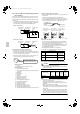
(7)-1 IN CASE OBSTACLES EXIST ONLY IN FRONT OF THE
AIR INLET
When nothing is obstructing the top
1.
Installation of single unit
• In case obstacles exist only in front of the air inlet
(Refer to figure 4-[1])
• In case obstacles exist in front of the air inlet and on both sides
of the unit (Refer to figure 4-[2])
Name Regarding use Installation manual Binding band
Quantity 1 1 6 pcs.
Shape
Name
Gas side
accessory pipe (1)
Gas side
accessory pipe (2)
Gas side
accessory pipe (3)
Quantity 1 pc. 1 pc. 1 pc.
Shape
Name Insulation tube
Quantity 1 pc. 1 pc.
Shape
REFNET joint KHRP26M22T
(large)
(small)
01_EN_3P329623-1.fm Page 4 Friday, November 9, 2012 6:50 PM