
RMXS48LVJU Installation Manual


5 English
2.
In case of installing multiple units (2 units or more) in lateral con-
nection per row
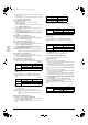
• In case obstacles exist in front of the air inlet and on both sides
of the unit (Refer to figure 4-[3])
When something is obstructing the top
1.
Installation of single unit
• In case obstacles exist only in front of the air inlet
(Refer to figure 5-[1])
• In case obstacles exist in front of the air inlet and on both sides
of the unit (Refer to figure 5-[2])
2.
In case of installing multiple units (2 units or more) in lateral con-
nection per row
• In case obstacles exist in front of the air inlet and on both sides
of the unit (Refer to figure 5-[3])
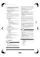
(7)-2 IN CASE OBSTACLES EXIST IN FRONT OF THE OUTLET
SIDE
When nothing is obstructing the top
1.
Installation of single unit (Refer to figure 6-[1])
2.
In case of installing multiple units (2 units or more) in lateral con-
nection per row (Refer to figure 6-[2])
When something is obstructing the top
1.
Installation of single unit (Refer to figure 6-[3])
2.
In case of installing multiple units (2 units or more) in lateral con-
nection per row (Refer to figure 6-[4])
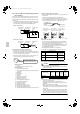
(7)-3 IN CASE OBSTACLES EXIST IN FRONT OF BOTH THE
AIR INLET AND OUTLET SIDES
Pattern 1: Where obstacle in front of the air outlet is higher than the
unit.
(There is no height limit for obstructions on the intake side.)
When nothing is obstructing the top
1.
Installation of single unit (Refer to figure 7-[1])
2.
In case of installing multiple units (2 units or more) in lateral con-
nection per row (Refer to figure 7-[2])
When something is obstructing the top
1.
Installation of single unit (Refer to figure 7-[3])
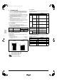
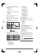
Relation of dimensions of H, A, and L are shown in the table below.
inch (mm)
Note
Get the lower part of the frame sealed so that air from the outlet
does not bypass.
2.
Series installation (up to 2 units) (Refer to figure 7-[4])
Relation of dimensions of H, A, and L are shown in the table
below.
inch (mm)
Note
1. Get the lower part of the frame sealed so that air from the out-
let does not bypass.
2. Only two units at most can be installed in series.
Pattern 2: Where obstacles in front of the air outlet is lower than the
unit.
(There is no height limit for obstructions on the intake
side.)
When nothing is obstructing the top
1.
Installation of single unit (Refer to figure 7-[5])
2.
In case of installing multiple units (2 units or more) in lateral con-
nection per row (Refer to figure 7-[6])
Relation of dimensions of H, A, and L are shown in the table
below.
inch (mm)
When something is obstructing the top
1.
Installation of single unit (Refer to figure 7-[7])
Relation of dimensions of H, A, and L are shown in the table
below.
inch (mm)
Note
Get the lower part of the frame sealed so that air from the outlet
does not bypass.
2.
Series installation (up to 2 units) (Refer to figure 7-[8])
Relation of dimensions of H, A, and L are shown in the table
below.
inch (mm)
Note
1. Get the lower part of the frame sealed so that air from the out-
let does not bypass.
2. Only 2 units at most can be installed in series.
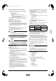
(7)-4 IN CASE OF STACKED INSTALLATION
1.
In case obstacles exist in front of the outlet side
(Refer to figure 8-[1])
Note
1. No more than 2 units should be stacked.
2. About 4 inch (100 mm) is required as the dimension for laying
the upper outdoor unit’s drain pipe.
3. Shut off the Z part (the area between the upper outdoor unit
and the lower outdoor unit) so that outlet air does not bypass.
2.
In case obstacles exist in front of the air inlet
(Refer to figure 8-[2])
Note
1. No more than 2 units should be stacked.
2. About 4 inch (100 mm) is required as the dimension for laying
the upper outdoor unit’s drain pipe.
3. Shut off the Z part (the area between the upper outdoor unit
and the lower outdoor unit) so that outlet air does not bypass.
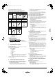
(7)-5 IN CASE OF MULTIPLE-ROW INSTALLATION (FOR ROOF
TOP USE, ETC.)
1.
In case of installing 1 unit per row (Refer to figure 9-[1])
2.
In case of installing multiple units (2 units or more) in lateral con-
nection per row (Refer to figure 9-[2])
Relation of dimensions of H, A, and L are shown in the table
below.
inch (mm)
LA
L
≤
H
0 < L
≤
1/2H 30 (750)0
1/2H < L
≤
H 40 (1000)
H < L
Set the frame to be L ≤ H
LA
L
≤
H
0 < L
≤
1/2H 40 (1000)
1/2H < L
≤
H 50 (1250)
H < L
Set the frame to be L ≤ H
LA
0 < L
≤
1/2H 10 (250)
1/2H < L
≤
H12 (300)
LA
L
≤
H
0 < L
≤
1/2H 4 (100)
1/2H < L
≤
H 8 (200)
H < L
Set the frame to be L ≤ H
LA
L
≤
H
0 < L
≤
1/2H 10 (250)
1/2H < L
≤
H12 (300)
H < L
Set the frame to be L ≤ H
LA
L
≤
H
0 < L
≤
1/2H 10 (250)
1/2H < L
≤
H12 (300)
H < L
Installation impossible.
01_EN_3P329623-1.fm Page 5 Friday, November 9, 2012 6:50 PM