
RMXS48LVJU Installation Manual

English 6
5. PRECAUTIONS ON INSTALLATION
• Install making sure the unit is level and the foundation is sturdy
enough to prevent vibration noise.
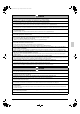
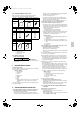
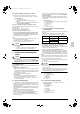
• In accordance with the foundation drawing in figure 10, fix the unit
securely by means of the foundation bolts.
(Prepare 4 sets of M12 foundation bolts, nuts and washers each
which are available on the market.)
• The foundation bolts should be inserted 15/16 inch (20 mm).
(Refer to figure 10)
1. Diagram of lower surface
<Drain pipe disposal>
• Locations where drainage from the outdoor unit might be a prob-
lem.
In such locations, for example, where the drainage might drip onto
passersby, lay the drain piping using the separately sold drain
plug.
• When laying the drain, at least 4 inch (100 mm) from the bottom of
the outdoor unit is needed.
• Make sure the drain works properly.
(Watch out for water leaks if piping is brought out the bottom.)
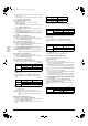
(Refer to figure 11)
1. Drain plug
2. 4 tabs
3. Drain receiver
4. Insert the drain receiver as far as possible into the drain
plug and hook the tabs.
5. Bottom frame drain hole
6. (1) Insert the drain plug through the drain hole in the
bottom frame shown in figure 12.
(2) Turn the drain plug along the guides until it stops
(approx. 90°), and then attach the bottom frame.
7. Guide
(Refer to figure 12)
1. Air outlet side
2. Diagram of lower surface
3. Drain hole
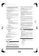
[How to remove the transport clasp]
• A yellow transport clasp and washer are attached to the legs of
the compressor to protect the unit during transportation, so
remove them as shown in figure 13.
(Refer to figure 13)
1. Compressor
2. Securing nut
3. Washer
4. Transport clasp
5. Turn in the direction of the arrow and remove.
6. Sound-proof cover
7. Do not remove with the cover open.
(1) Open the sound-proof cover as shown in figure 13.
Do not pull the sound-proof cover or remove it from the compres-
sor.
(2) Remove the securing nut.
(3) Remove the washer.
(4) Remove the transport clasp as shown in figure 13.
(5) Retighten the securing nut.
(6) Return the sound-proof cover as it was.
6. FIELD WIRING
CAUTION
To the electrician
• Do not operate until refrigerant piping work is completed.
(If operated before complete the piping work, the compressor
may be broken down.)
• Be sure to install a ground fault circuit interrupter.
(This unit uses an inverter, so install the ground fault circuit inter-
rupter that be capable of handling high harmonics in order to
prevent malfunctioning of the ground fault circuit interrupter
itself.)
6-1 Wiring connection example for whole system
• Electrical wiring work should be done by a certified professional.
• Follow the “Electrical wiring diagram face plate” when carrying out
any electrical wiring.
Only proceed with wiring work after blocking off all power.
• Make sure the ground resistance is no greater than 4Ω .
• Attach a ground-fault circuit interrupter.
• Ground the indoor and outdoor units.
• Do not connect the ground wire to gas pipes, sewage pipes, light-
ning rods, or telephone ground wires.
• Gas pipes: can explode or catch fire if there is a gas leak.
• Sewage pipes: no grounding effect is possible if hard plastic
piping is used.
• Telephone ground wires and lightning rods: dangerous
when struck by lightning due to abnormal rise in electrical poten-
tial in the grounding.
• Use copper wire.
• When doing the electrical wiring, always shut off the power source
before working, and do not turn on the switch until all work is com-
plete.
• This unit has an inverter, so it must be grounded in order to reduce
noise and prevent it affecting other appliances, and also to
release any electrical build-up in the unit case due to leaked cur-
rent.
• Do not install a power-factor improving phase-advancing capaci-
tor under any circumstances.
(Not only will this not improve the power factor, but it might cause
a fire.)
• Connect the wire securely using designated wire and fix it with
attached clamp without applying external pressure on the termi-
nal parts (terminal for power wiring, terminal for transmission wir-
ing and ground terminal). See “6-3 How to connect the power
supply wiring”.
• Left-over wiring should not be wrapped and stuffed into the unit.
• To prevent the power wiring from being damaged by the knock
hole edges, put it in a wiring pipe or plastic tube to protect it.
• Secure the wiring with the included clamp so that it does not come
in contact with the piping or stop valve.
(See “6-3 How to connect the power supply wiring”.)
CAUTION
• Use a power wire pipe for the power supply wiring.
• Outside the unit, make sure the weak electric wiring (i.e. for the
remote controller cord, between units, etc.) and the strong elec-
tric wiring do not pass near each other, keeping them at least
2 inch (50 mm) apart.
Proximity may cause electrical interference, malfunctions, and
breakage.
• Be sure to connect the power wiring to the power wiring terminal
block and secure it as described in “6-3 How to connect the
power supply wiring”.
• Inter-unit wiring should be secured as described in “6-4 Inter-
unit wiring connection procedure”.
• Secure wiring with binding band (accessory) to avoid contact
with piping.
• Make sure the wiring and the front panel do not stick up above
the structure, and close the cover firmly.
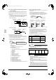
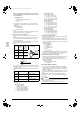
(Refer to figure 14)
1. The power source is supplied to each BP unit
individually.
2. Branch switch and over-current interrupter (ground-fault
circuit interrupter)
3. Power supply
4. Outdoor unit
5. 16V
6. 208/230V
7. Indoor unit
8. BP unit
9. Ground wire
01_EN_3P329623-1.fm Page 6 Friday, November 9, 2012 6:50 PM