
RMXS48LVJU Installation Manual

7 English
6-2 How to lay the power supply wiring and trans-
mission wiring
Let the power supply wiring and transmission wiring with a conduit
pass through one of the knockout holes on the front or side cover,
and let the transmission wiring with a conduit pass through another
knockout hole.
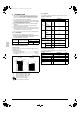
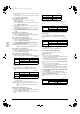
• For protection from uninsulated live parts, thread the power sup-
ply wiring and the transmission wiring through the included insu-
lation tube and secure it with the included binding band.
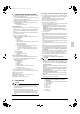
Precautions when knocking out knock holes
• Open the knock holes with a hammer or the like.
• After knocking out the holes, we recommend you remove burrs in
the knock holes and paint the edges and areas around the edges
using the repair paint to prevent rusting.
• When passing wiring through knock holes, make sure there are
no burrs, and protect the wiring with protective tape.
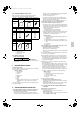
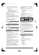
(Refer to figure 15)
1. Screw
2. Unfasten the screw and open the cover.
(Refer to figure 16)
1. Stop valve attachment plate
2. Power supply wiring (including ground wire) or transmis-
sion wiring.
3. Backward
4. Knockout hole
5. Sideways
6. Forward
7. Electrical Component Box
8. Terminal block (X2M)
9. Binding band (accessory)
10. Connecting power supply wiring
11. Ground wire (yellow/green)
12. Terminal block (X1M)
13. Transmission wiring
14. (To X2M [To BP unit] (F1, F2))
15. Insulation tube (large) (accessory)
16. Insulation tube (small) (accessory)
17. Cut off the insulation tube sticking out of the outdoor unit.
<Precautions when laying power wiring>
• Wiring of different thicknesses cannot be connected to the power
terminal block.
(Slack in the power wiring may cause abnormal heat.)
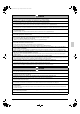
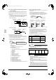
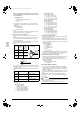
• Use sleeve-insulated round pressure terminals for connections to
the power terminal block. When none are available, connect wire
of the same diameter to both sides, as shown in the figure.
Follow the instructions below if the wiring gets very hot due to
slack in the power wiring.
• For wiring, use the designated power wire and connect firmly,
then secure using the included clamping material to prevent out-
side pressure being exerted on the terminal block.
• Use an appropriate screwdriver for tightening the terminal screws.
A screwdriver with a small head will strip the head and make
proper tightening impossible.
• Over-tightening the terminal screw may break it.
See the table below the tightening torque of the terminal screws.
6-3 How to connect the power supply wiring
CAUTION
Attach a ground-fault circuit interrupter.
• A ground-fault circuit interrupter is required in order to prevent
electric shock and fires.
CAUTION
• The wiring should be selected in compliance with local specifi-
cations. See the table above.
• Always turn off the power before doing wiring work.
• Grounding should be done in compliance with local laws and
regulations.
• Attach a ground-fault circuit interrupter.
(This unit has an inverter, so an interrupter capable of handling
high frequencies is needed to prevent malfunction of the inter-
rupter itself.)
• As shown in figure 16, when connecting the power supply wiring
to the power supply terminal block, be sure to clamp securely.
• Once wiring work is completed, check to make sure there are no
loose connections among the electrical parts in the control box.
Insulation tube
(accessory)
Binding band
(accessory)
Power supply
wiring
3 inch
(76mm)
5/8 inch
(15 mm)
2 inch
(50 mm)
or more
5/8 inch
(15 mm)
Insulation tube
(accessory)
Binding band
(accessory)
Transmission
wiring
3 inch (76mm)
<Power supply wiring>
<Transmission wiring>
Ground wire
If small animals might enter the
unit, block the knock holes with an
appropriate material (field supply).
Burr
Tightening torque
M5 Power terminal
1.76-2.15 ft·lbf
(2.39-2.91 N·m)
M4 Shield ground
0.87-1.06 ft·lbf
(1.18-1.44 N·m)
M3
Transmission wiring terminal block
0.58-0.72 ft·lbf
(0.8-0.97 N·m)
Model name
Frequency Voltage
Rated
current
for fuses
Maximum
outdoor unit
operating
current
RMXS48LVJU 60Hz 208/230V 30A 27A
Insulating sleeve
Round crimp-style
terminal
Electric Wire
Connect wires
of the same gauge
to both side.
Do not connect
wires of different
gauges.
Do not connect
wires of the same
gauge to one side.
Good Wrong
Wrong
01_EN_3P329623-1.fm Page 7 Friday, November 9, 2012 6:50 PM