
RMXS48LVJU Installation Manual

English 8
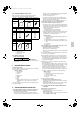
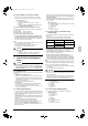
6-4 Inter-unit wiring connection procedure
• Between indoor units in the same system, pass the wiring
between the units as shown in figure 17. (There is no polarity.)
(Refer to figure 17)
1. Terminal block (X2M)
2. Use balance type shield wire (with no polarity).
3. BP unit
4.
Not used for this model.
Never connect wires, or the
entire system will be damaged.
Precautions regarding the length of wiring between units
Exceeding the following limits may cause transmission malfunctions,
so observe them.
Max. wiring length Max. 656 ft (200 m)
Total wiring length Max. 984 ft (300 m)
Precautions regarding wiring between units
• Do not connect 208/230V power wiring to terminals for the
inter-unit wiring. Doing so would destroy the entire system.
• Wiring to the BP unit should be wired to F1 and F2 (To BP unit) on
the outdoor unit’s terminal block (X2M).
Note
• The above wiring should be wired using AWG 18-16 (0.75 – 1.25
mm
2
) shielded (balance type) wiring.
(See figure 16 for how to ground the shielded parts.)
• All inter-unit wiring is to be procured on site.
CAUTION
(Refer to figure 18)
1. Branch
2. Caution on branches in the wiring among BP units
3. The following branches can not be performed
7. PRECAUTIONS ON REFRIGERANT
PIPING
CAUTION
To the pipe-layer
• Do not operate the unit with the transport clasp attached. This
can cause abnormal shaking or noise. See “5. PRECAUTIONS
ON INSTALLATION” and “How to remove the transport clasp”.
7-1 Installation tools
Use the right parts to ensure tolerance and to prevent foreign matter
for entering.
Gauge manifold, charge hose, etc.
• Make sure to use installation tools that are exclusively used for
R410A installations to withstand the pressure and to prevent for-
eign materials (e.g. mineral oils such as SUNISO and moisture)
from mixing into the system.
(The screw specifications differ for R410A.)
Vacuum pump
• Use extreme caution to prevent pump oil from flowing back-
wards through the system when the pump is stopped.
• Use a vacuum pump which can evacuate to –14.6 PSI (–100.7
kPa (5Torr, –755mmHg)).
7-2 Selecting piping material
•
Use pipes that have no contaminants adhered to their inner surfaces
(such as sulfur, iron oxide, dust, cutting chips, oil and moisture). (It is
desirable that adhered oil inside the piping is 0.00006 lb. (30 mg) or
less per 32.8 ft (10 m).)
•
The wall thickness of the refrigerant piping should comply with local
laws and regulations. The design pressure for R410A is 478 PSI
(3.3 MPa).
• Use the following material for the refrigerant piping.
Material: Jointless phosphor-deoxidized copper pipe.
• Thickness and size: choose based on the piping size selection
method on the “7-8 Air tight test and vacuum drying”.
• Make sure to use the separately sold refrigerant branch kit when
branching the piping.
• Piping work should be done within the maximum length, height
difference, and length after branches set out in “7-8 Air tight test
and vacuum drying”.
• Install the refrigerant branch kit while observing the following con-
dition and referring to the installation manual offered as an acces-
sory of the kit.
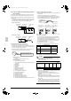
(Refer to figure 19)
1.
Install the REFNET joint so it splits horizontally or vertically.
2. Horizontal surface
3. A-arrow view
4. ±30° or less
5. Level
6. Vertical is also OK
7-3 Protection against contamination when
installing pipes
• Wrap the piping to prevent moisture, dirt, dust, etc. from entering
the piping.
• Exercise caution when passing copper piping through the
through-holes and when passing them out to the outside.
7-4 Pipe connection
• See “Stop valve operation procedure” in “7-8 Air tight test and
vacuum drying” regarding handling of the stop valve.
• Only use the flare nuts included with the unit. Using different flare
nuts may cause the refrigerant to leak.
• Be sure to perform a nitrogen blow when brazing.
(Brazing without performing nitrogen replacement or releasing
nitrogen into the piping will create large quantities of oxidized film
on the inside of the pipes, adversely affecting valves and compres-
sors in the refrigerating system and preventing normal operation.)
Note
The nitrogen used when brazing while flowing the nitrogen should be
set to 2.9 PSI (0.02 MPa) (2.8 PSI / 0.019 MPa: just enough to feel a
breeze on your cheek) with the decompression valve.
• Do not mix any refrigerant other than that specified into the refrig-
erant system.
• Do not mix air into the refrigerant system.
CAUTION
Do not use a flux when brazing the refrigerant pipe joints.
Use phosphor copper brazing (BCuP-2/B-Cu93P-710/795) which
does not require flux.
(Using a chlorine flux may cause the pipes to corrode, and if it
contains fluoride it may cause the refrigerant lubricant to deterio-
rate, adversely affecting the refrigerant piping system.)
(Refer to figure 20)
1. Refrigerant pipe
2. Location to be brazed
3. Regulator
4. Nitrogen
5. Manual valve
6. Taping
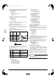
7-5 Connecting the refrigerant piping
• The local inter-unit piping is connectable in four directions.
(Refer to figure 21)
1. Front panel
2. Pipe outlet panel
3. Backward
4. Sideways
5. Downward
6. Pipe outlet panel screw
7. Forward
8. Screw for front panel
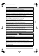
Place Installation period Protection method
Outdoor
More than a month Pinch the pipe
Less than a month
Pinch or tape the pipe
Indoor Regardless of the period
01_EN_3P329623-1.fm Page 8 Friday, November 9, 2012 6:50 PM